Jedi, Sith, starfighters, walkers, whatever. No one could argue that the true hero of the Star Wars universe is the homely GR-75 medium transport. Cheap, poorly built, cargo literally simply floating in the void, well past due for retirement, clean lines marred by all manner of greeblies, hull panels invariably burned through… I love it.
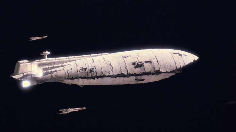
A GR-75 evacuating Rebels from Hoth, escorted by X-Wings.
 Not unrelated, wargaming is all about supply containers and cargo bits. “Buck up, soldier, we’re shipping you across the galaxy to fight horrible monsters over… some oil drums… and maybe a weapons crate.” So in crafting missions for our Molokh Gambit X-Wing Miniatures narrative campaign event, of course there’s going to be a Supply Depot scenario.
Just like the shuttle mission, that means we need cool tokens for the mission. A couple good 3D printable options already exist. There’s a great 3D rendition of the art on the Den of Thieves scenario tokens that come with the Millenium Falcon (remixed here to be printable w/ no supports). At a larger size is the Class A container from the X-Wing and TIE Fighter video games, which has also been made into a BFF-1 Bulk Freighter.
Neither of those worked for me though. I wanted something that could be printed without needing to cut supports or glue halves, was small like the container token to minimize impact on the basic game dynamics, and ideally had fewer Imperial associations. So I modeled the cargo pods on the underside of FFG’s GR-75 model.
This tutorial is a walkthrough of that, in hopes that newcomers to 3D modeling and printing might learn from seeing the process of constructing this simple artifact. These designs have also been uploaded to Thingiverse as a free download. In addition, I have a previous article up more generally introducing 3D printing for miniatures.
It’s a hunk of falling-apart junk, so of course the Rebels would decide the transport could do double duty as an assault ship…
Shape
Fantasy Flight’s GR-75 model is really fun. There’s a ton of detail, and just enough color to really draw the eye onto them. Most captivating is the underside, with a whole mess of tiny cargo pods sprinkled with bright colors. It’s exquisite.
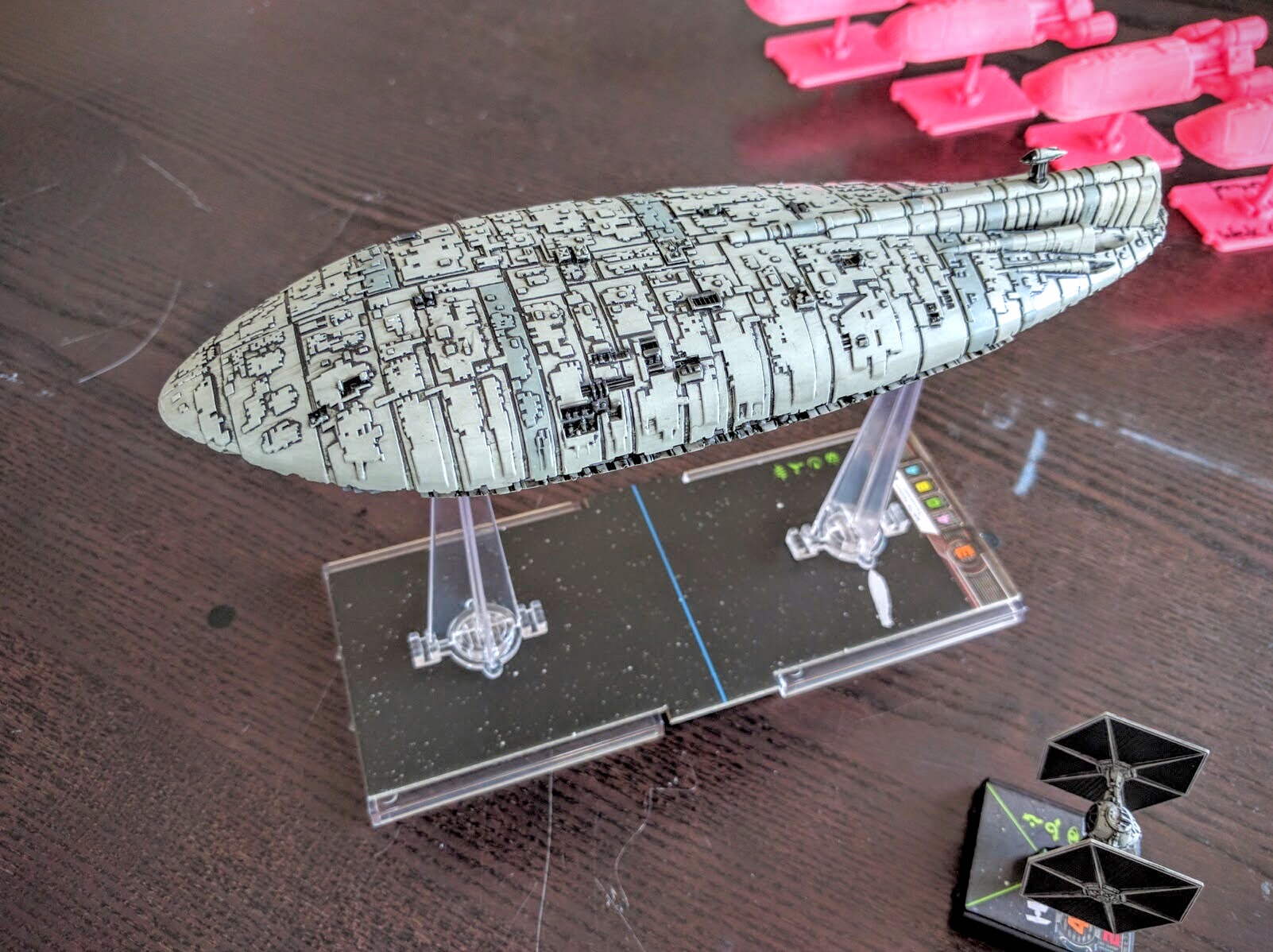
Fantasy Flight’s GR75 model.
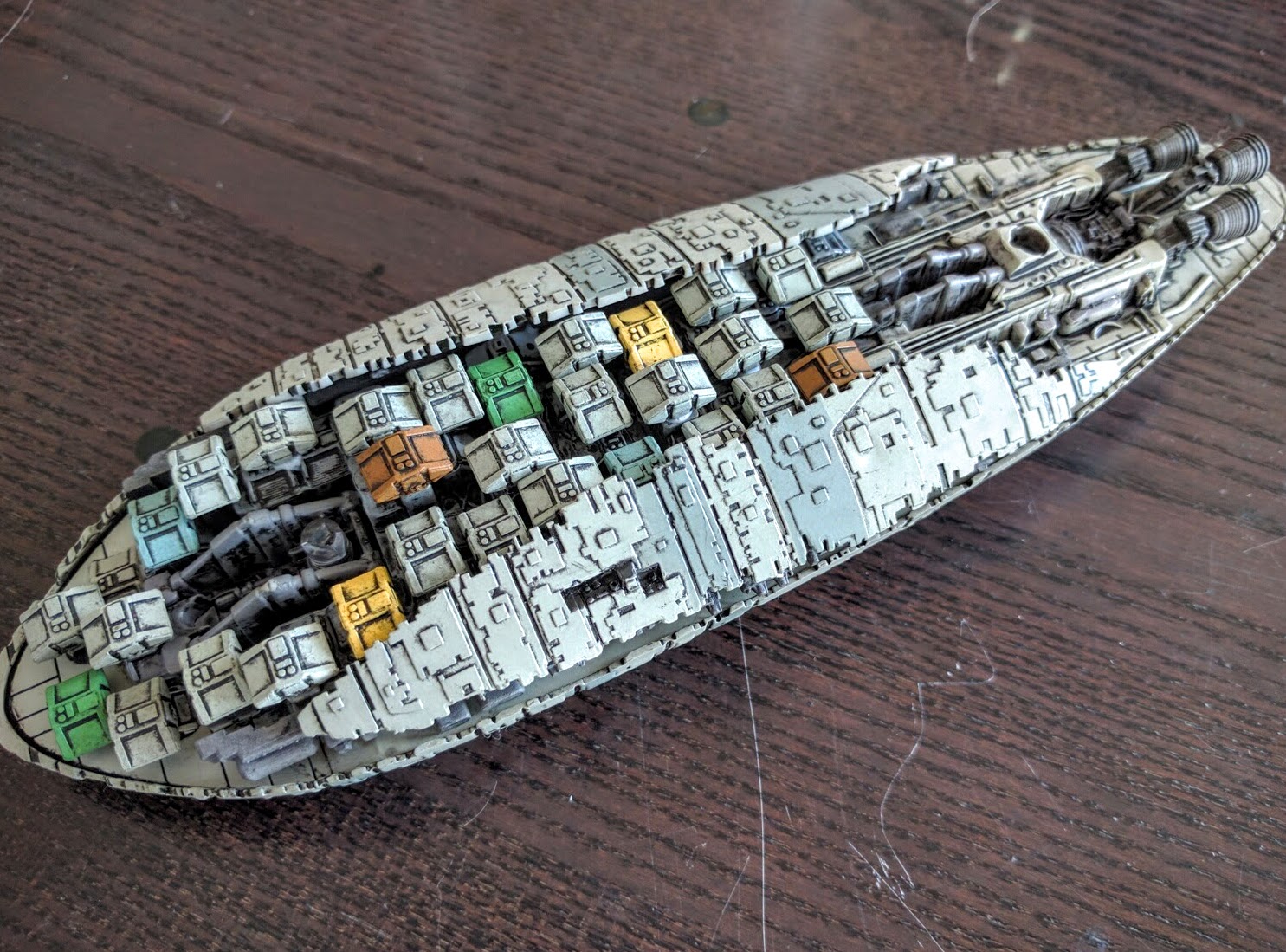
Pods filling the underside cargo bay of the medium transport.
Fortunately for my task here, these pods have a distinctive but really simple design:
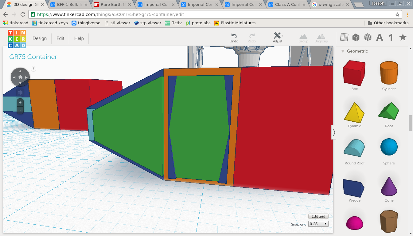
- The core shape is basically a central box with two large angled wings;
- The wings are themselves top and bottom triangles with a thin central box;
- There are recesses on the top and bottom of the wings;
- The front and back faces have pads with slightly angled corner cutouts;
- The top is textured with two boxes and two circles.
Easy. The one detail I opted to skip is that the front and back faces have slight angles to their top and bottom halves. This feature would be a hassle for me to model, the loss of it wouldn’t really impair the look, and it’s probably largely a production requirement. Vertical faces of plastic injection molded parts have to be drafted (swept back) so that the piece doesn’t get stuck in the die or the metal scrape across and mar the surface as the two halves of the mold are pulled apart and the component ejected. That’s probably the primary driver of why these faces are angled. This isn’t a concern in 3D printing however, as the part is formed in place with no encasing mold.
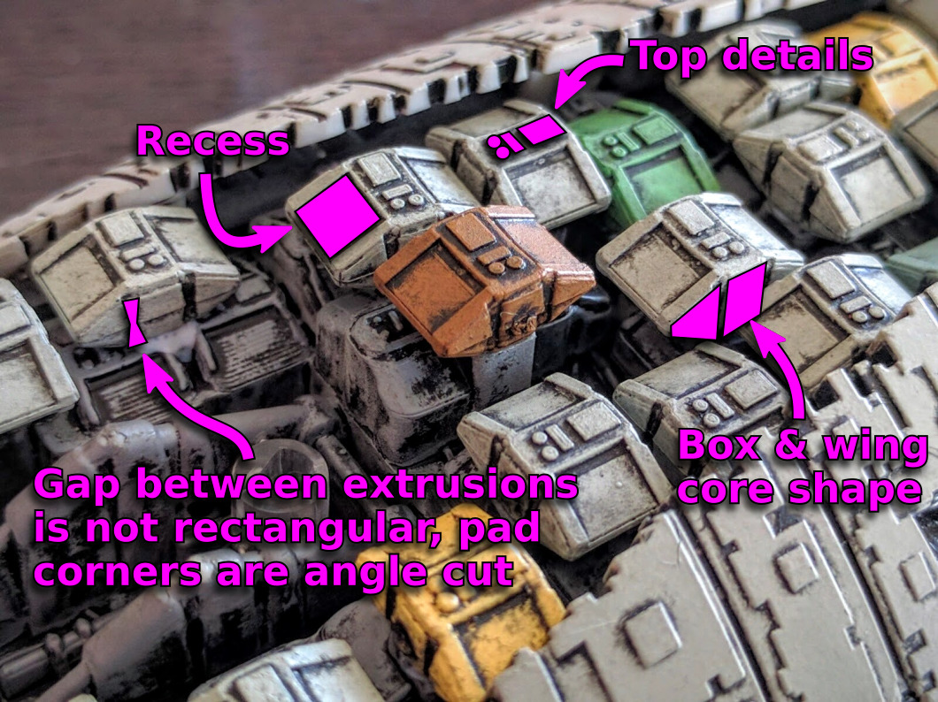
Cargo pod deconstruction.
Scale
With that shape deconstruction, the next question is “How big?” I decided to upscale my cargo pods to 1/270, the nominal scale of X-Wing’s large and small ships. The huge ships, like the GR-75, are done at a mix of scales to tradeoff between manufacturability, cost, gameplay, and look. As you might guess, this is a whole huge topic area online that dives way deep into the “correctness” of FFG’s models versus previously published material, with many lists around cataloging the variances.
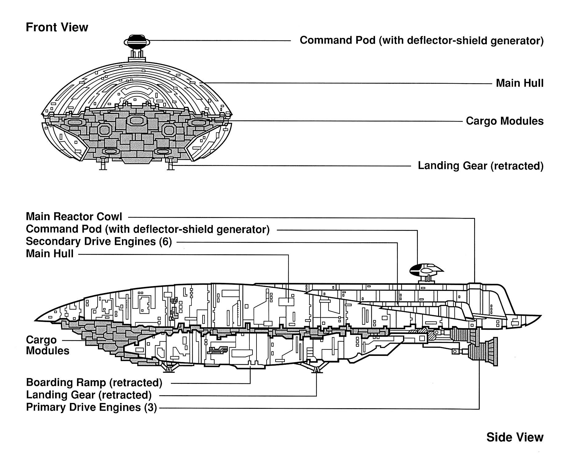
In this case, there are no concrete canonical measurements for the GR-75. Length, width, etc., are not published in its starwars.com data bank entry, and they’ve never been given in authoritative roleplaying books, video games, and so on. A well established baseline though, derived from comparison to other ships and as reported by Wookieepedia, is that the “real world” transport is 90 meters long.
It fills me with no little joy that so many people have produced such serious documentation for so many Star Wars ships. #seriousbusiness!
FFG’s model is 225 millimeters long. Given the 90m length, that means it’s at exactly 1/400 scale (225mm/90,000mm = 1/400). If the model were done at the same 1/270 scale of the smaller ships, it would be 50% longer, 333mm. No doubt FFG decided that would cost too much to manufacture, even if the gameplay was reasonable—there’s only so big you can make a ship and still have it fly around on a kitchen table.
Moving on to the pods, I started by taking precise measurements of the overall extents as well as the vertical & horizontal central boxes. The pods were a little tricky to measure in place, and they no doubt vary a bit due to minute differences in cooling and plastic shrinking rates as they were cast, but some basic numbers are easily attained. Sampling a bunch of them, I came up with a range for each dimension. Those were roughly averaged and then upscaled by the trivial formula (observed * 400) / 270. That output I adjusted ad hoc to produce nice numbers. This isn’t rocket science, and it’s a lot easier to work with a 17mm wide piece than 16.59mm.
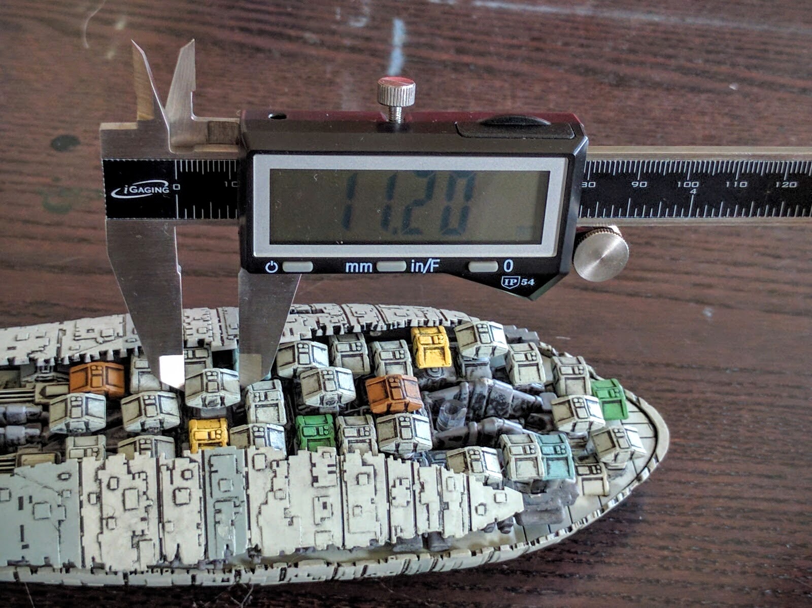
Measuring the pods.
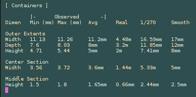
Working notes of observed measurements and calculations.
FFG’s 1/400 scale pods are about 11mm x 8mm x 5mm. Converting that to 1/270 scale, we get pods that are 17mm x 12mm x 8mm, with a 5mm central horizontal box, and a 2.5mm middle vertical box. In real life these would be 4.48m wide, 3.2m deep, and 2m tall. That seems inefficiently small for an interplanetary modular freight system, but not ridiculous. Those dimensions are just slightly bigger than the cargo space of a 15′ box truck (a meter is 3.28 feet). Regardless of real world issues, as a sanity check, that lines up with drawings and other representations of the GR-75 and how it gets loaded.
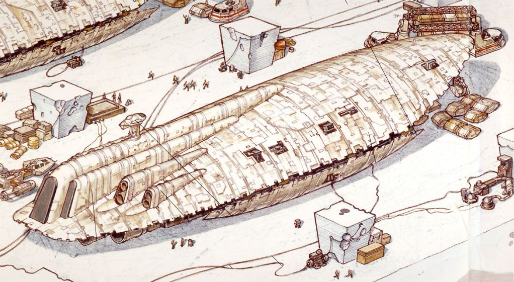
A GR-75 being loaded.
Modeling
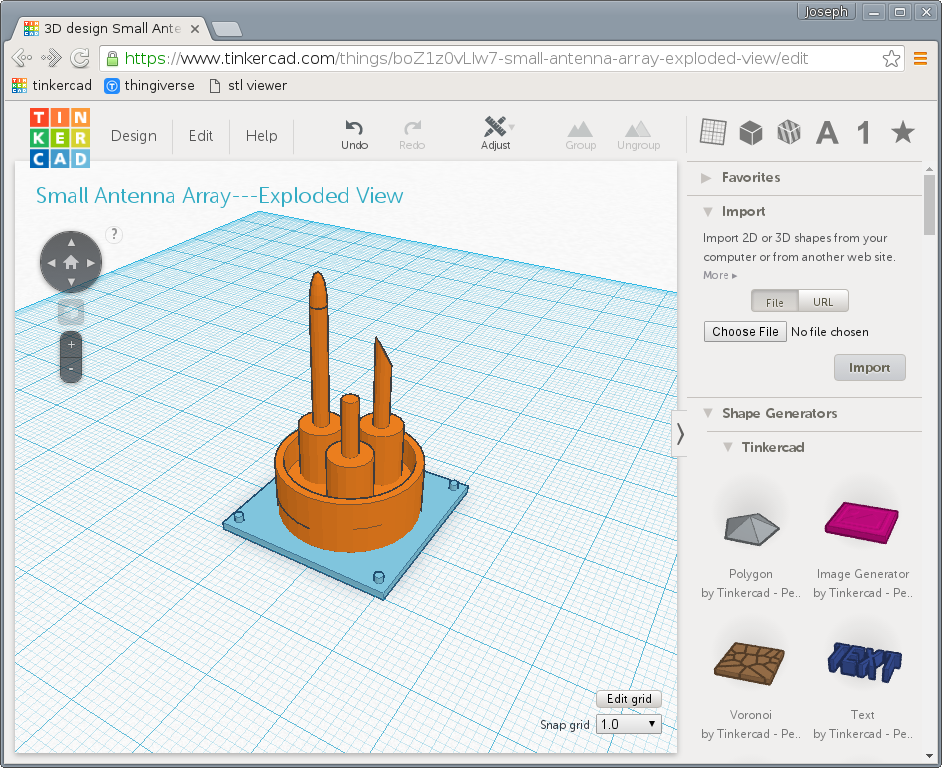
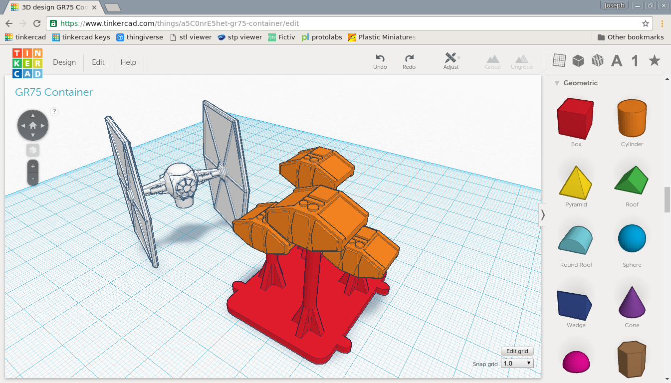
For a small project like this for 3D printing (as opposed to, say, laser cutting or injection molding), I’m a huge fan of TinkerCAD. It’s browser based, so unlike most CAD packages it works well on my Linux laptop. The interface is intuitive, and the feature set plenty for simple pieces. I was able to do a lot with it very quickly, and highly recommend the app. It’s free for non-commercial use, so you can try it out easily.
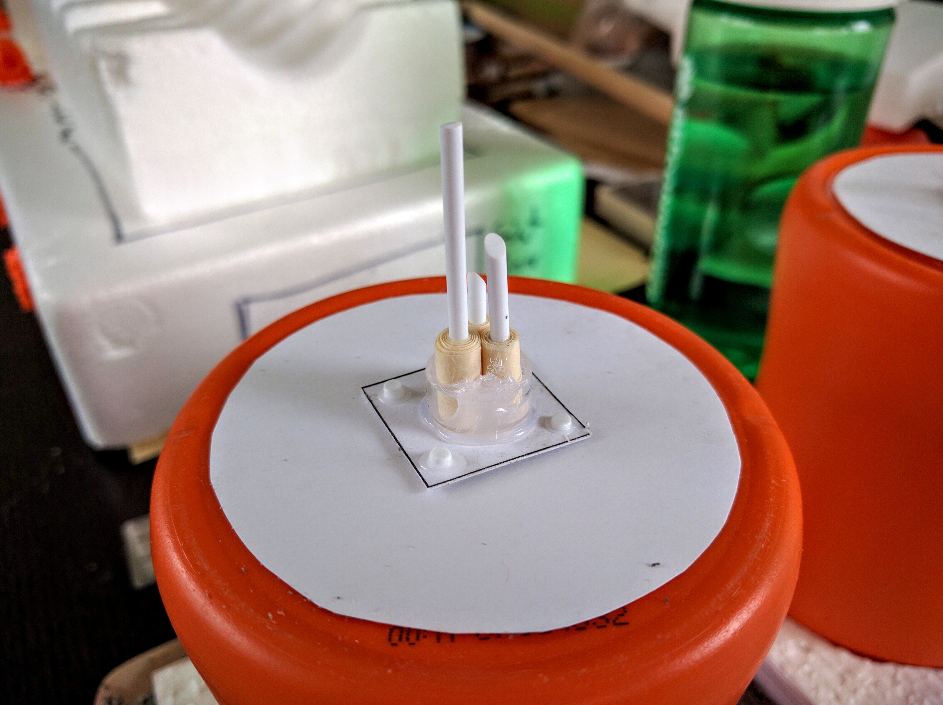
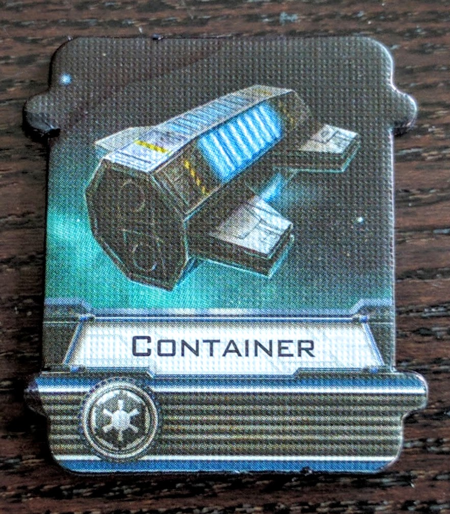
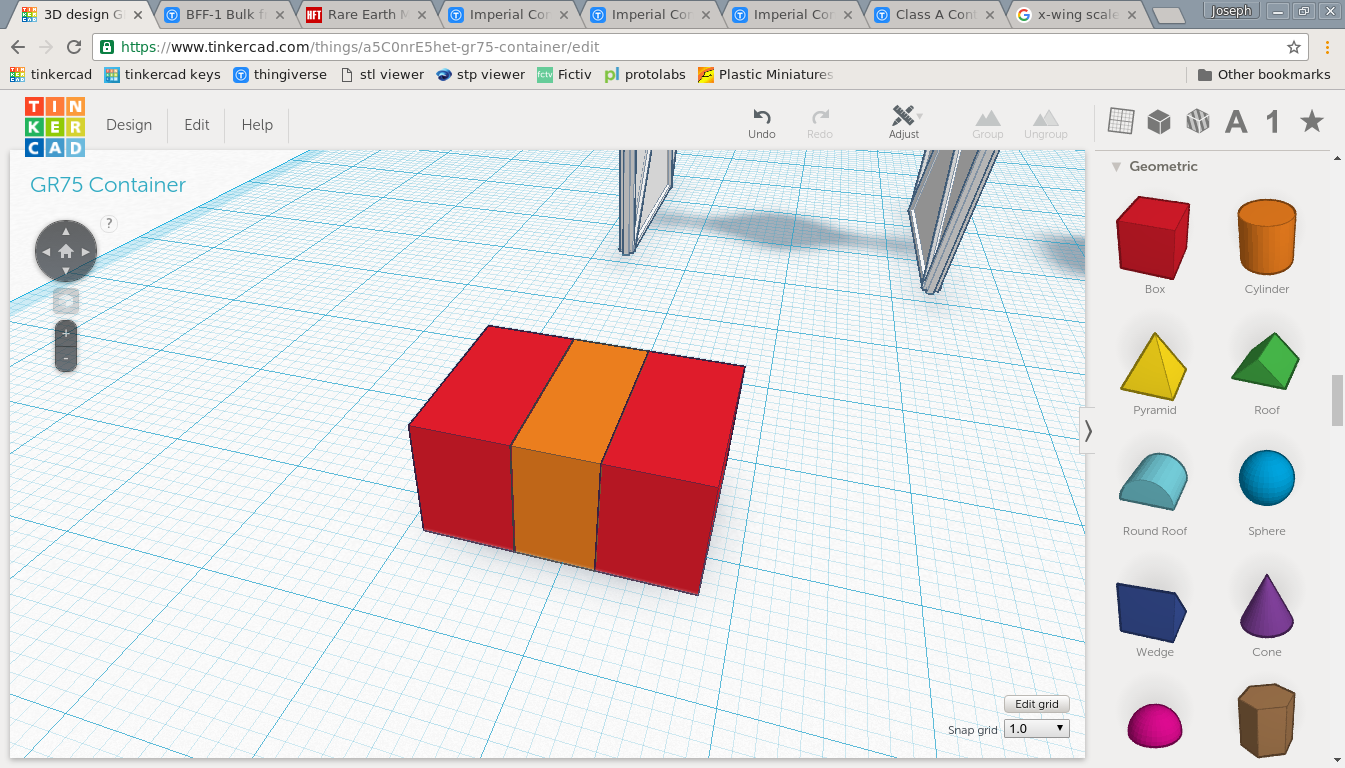
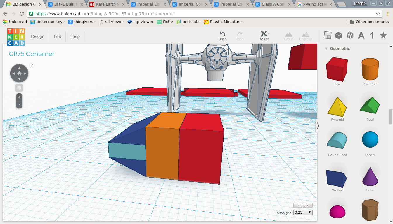
The first step in modeling the cargo pod was checking the overall dimensions, in case they needed to be fudged for gameplay or aesthetics. To start I made a base to exactly match the core set Container token. I wanted to keep that as the normative playing piece, with pods merely decoration. After making a box from the dimensions calculated above, I could see that it would be a reasonable size to put a couple on the base. In addition, I imported an X-Wing sized TIE Fighter model to see how the pod would look against a ship. It looks a bit small, but I think that’s an artifact of almost everyone picturing jet fighters and star fighters as much smaller than they are. This is especially true for the TIE Fighter, even setting aside FFG’s arguably upsized take on it.
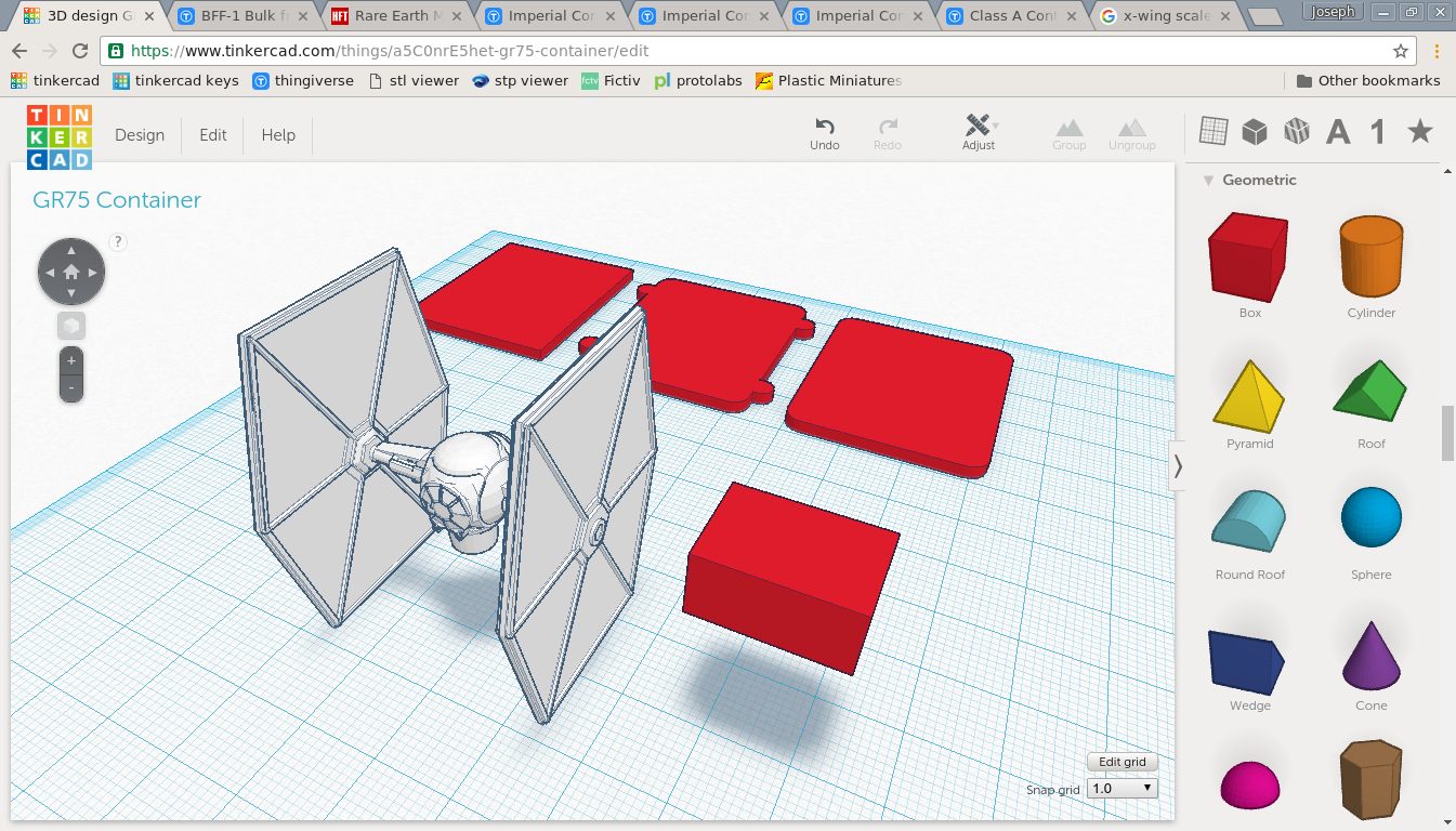
Roughing out the dimensions with an appropriately sized box.
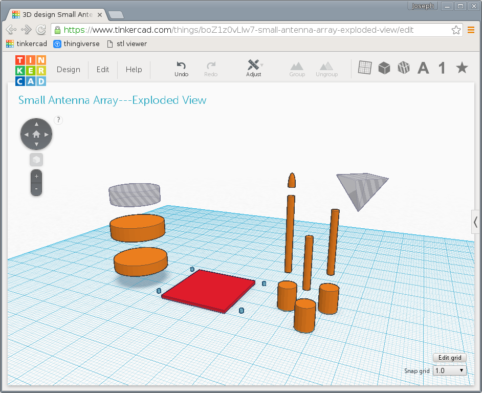
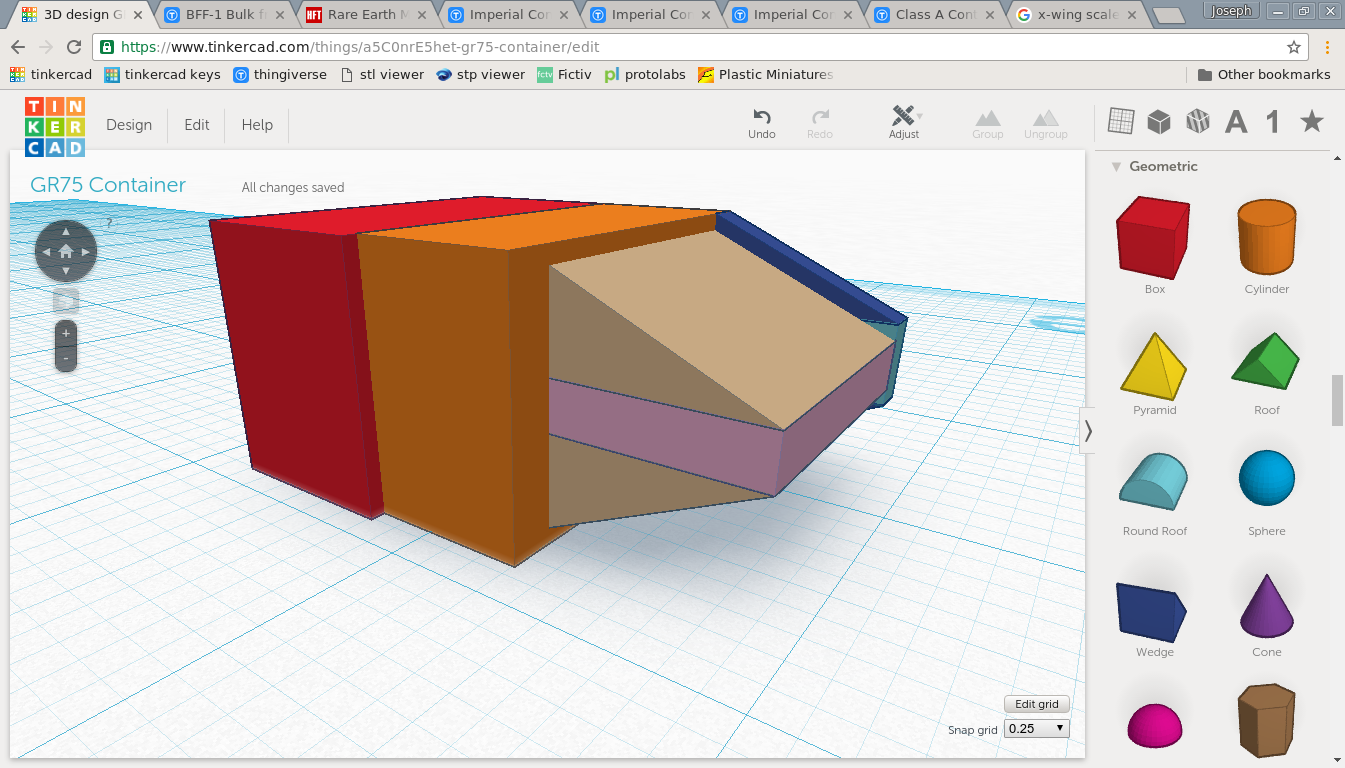
From there I blocked out the basic shape, creating three boxes capturing the overall dimensions of the center box and wings. The same was done for a wing, and then the top and bottom of it replaced with a wedge.The sizes for all of these boxes, notably implicitly defining the angle of the wings, were taken directly from the scale calculations above. Of course, I only needed to model a single wing in detail. As they’re the same left and right, when it was all done I could just duplicate and mirror that side.
Breaking the overall shape up into the central box and side wings.
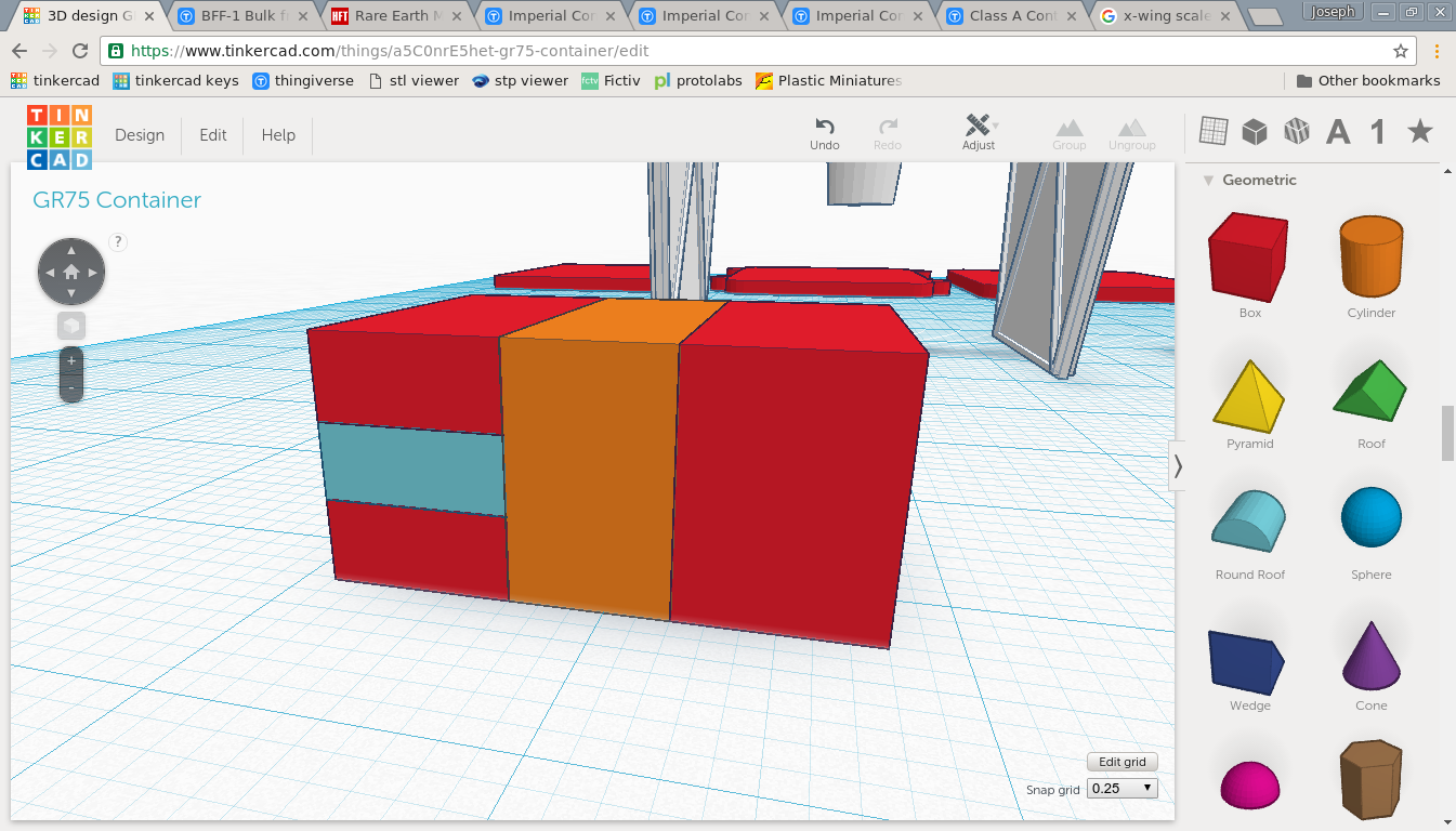
Deconstructing the wing into the middle box and two halves.
Replacing the top and bottom halves with wedges.
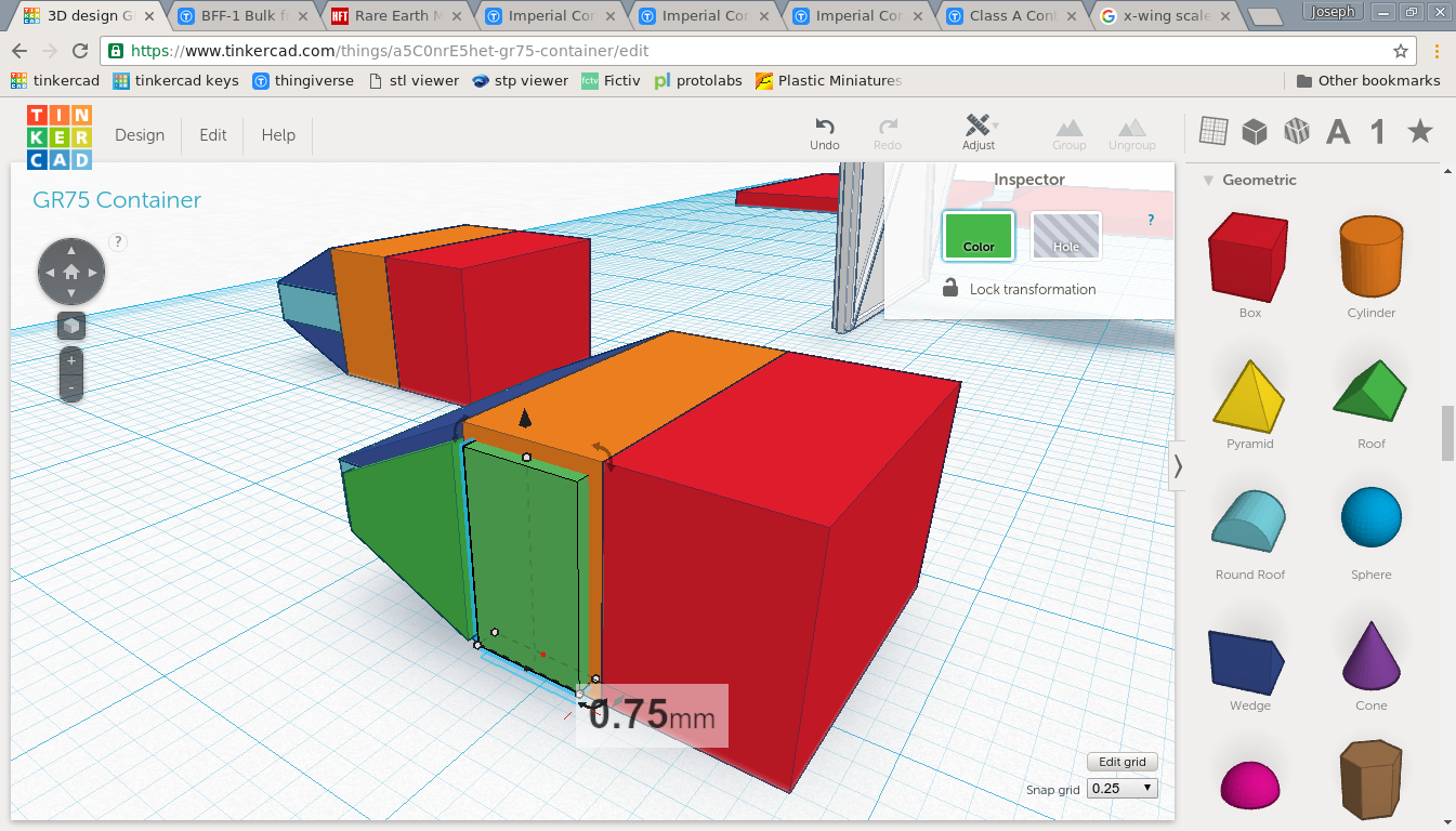
With the basic shape arranged, I made a checkpoint copy to keep in the background in case I decided to start over from this point, then started on the front pads. The center is simply a box slightly smaller than the center box itself. To make the side pad, I grouped the three components of the wing, duplicated the amalgam, shifted it forward, and scaled while maintaining aspect ratio. Both of these pads were sized and positioned to create a 0.5mm border around and between the pads.
The pads also stick out from the body 0.5mm, but they’re modeled 0.75mm deep and extend into the latter. A major issue in CAD system implementation and use is numerical precision. In particular, when shapes are combined to make a single solid, if two faces meet but are positioned apart by an infinitessimal decimal difference, the system may not realize they’re completely joined. It doesn’t typically matter much for this kind of casual modeling, the final printed piece would usually look the same either way. However, it could affect the efficiency of the print. It also quickly becomes an issue if you use a combined shape with such a gap as a hole to make a cut: You’ll be left with an extremely thin slice in the middle of the hole. I find this issue arises often in TinkerCAD, so whenever possible I extend parts into each other a bit to make absolutely clear that they should be a single solid when joined.
Another detail is that the 0.5mm visible pad depth is not an arbitrary value. Much below that and many home printers, including mine, would not have the resolution to be able to reliably produce the outline. Further, even if it could, the detail would be lost with all but a very careful paint job. The pads are also hanging in space, creating an overhang that might need external support to be printed. However, a 0.5mm overhang is easily managed by many or most slicers and printers. There’s little enough material that the overhanging region can be largely supported from the body.
Front pads made by copying the center box and wing, then scaling down and positioning.
A minute detail from the original piece, I then made very thin wedges to cut angles out of the corners of both pads. This is quickly done by making one wedge, then using the align and mirror tools to flip it into each corner. Those are then grouped together, switched to a hole, and grouped with the pad.
Wedges used as holes to cut corner angles into the front pads.
The recess on the wings could be made by scaling down the body similarly as the pads. However, a small tweak can be made to afford a critical difference. The front pad on the wing has a small border all around it. However, we can model the recess to only be on the top and bottom aspects. This is actually how it is on the FFG model: The side face of the wing body is aligned with the side extremity of the front and back ribs.
Modeling the recess this way is a significant boon to 3D printing the piece. By not recessing the side of the wing body, the side of the piece presents a completely flat plane. It’s also big enough to stand stably on the print platform. The piece can thus be rotated 90 degrees and printed on its side.
This is great news, because it entails no supports will be needed. If the piece were printed in its natural position, sitting upright, the wings would create an overhang requiring support. The issue is that the wings grow out to toward the sides at too shallow of an angle. The printer can’t print in thin air. Most start needing a support structure at anything shallower than a 45 degree overhang, and the wing rise is much less than that. Support structures are a pain to cut off or dissolve, assuming your printer even has the latter capability, so they’re best avoided whenever possible. They’re especially difficult to work on small pieces, and in this case the detail of the wing recess would be lost cutting out a same-material scaffold as required on a single-head fused deposition printer (the most common kind) on such a small piece.
Similarly, printing the piece on its front or back would risk losing the detail of the pads and their angle cuts. Although very small, the pads would create slight overhangs that might not be rendered as precisely. Even more likely, physical effects and common settings for the initial print layer(s) against the build plate, such as fatter and thicker material deposition, would probably cause the small recessed border around the pads and the detail of the angle cuts to be flattened, absorbed, or otherwise lost.
In contrast, by putting the piece on its flat side, no detail will be lost and the wing angles grow vertically very comfortably within printer tolerances. Combined with the point above about the front pad overhangs being kept well within tolerances, this means the piece can be printed without supports, and a whole mess of hassle and loss of detail avoided. As a bonus this mimics the original FFG piece as well, though it would otherwise be a tradeoff of printability versus accuracy well worth making anyway.
To preserve that flat side and create a solid print foundation with no supports needed, the wing body can’t be simply scaled down. Its body has to extend to the side extremity. So, rather than scaling, the original 3 piece wing construction was duplicated and ungrouped. The top and bottom wedges were then simply moved vertically toward the center, creating a border recess parallel to the top and bottom lines of the front and back ribs extending all the way to the side edge. The center box was then just downsized to this thinner space.
Similar to the pad, creating the wing recess by lowering the wedges and downsizing the middle box.
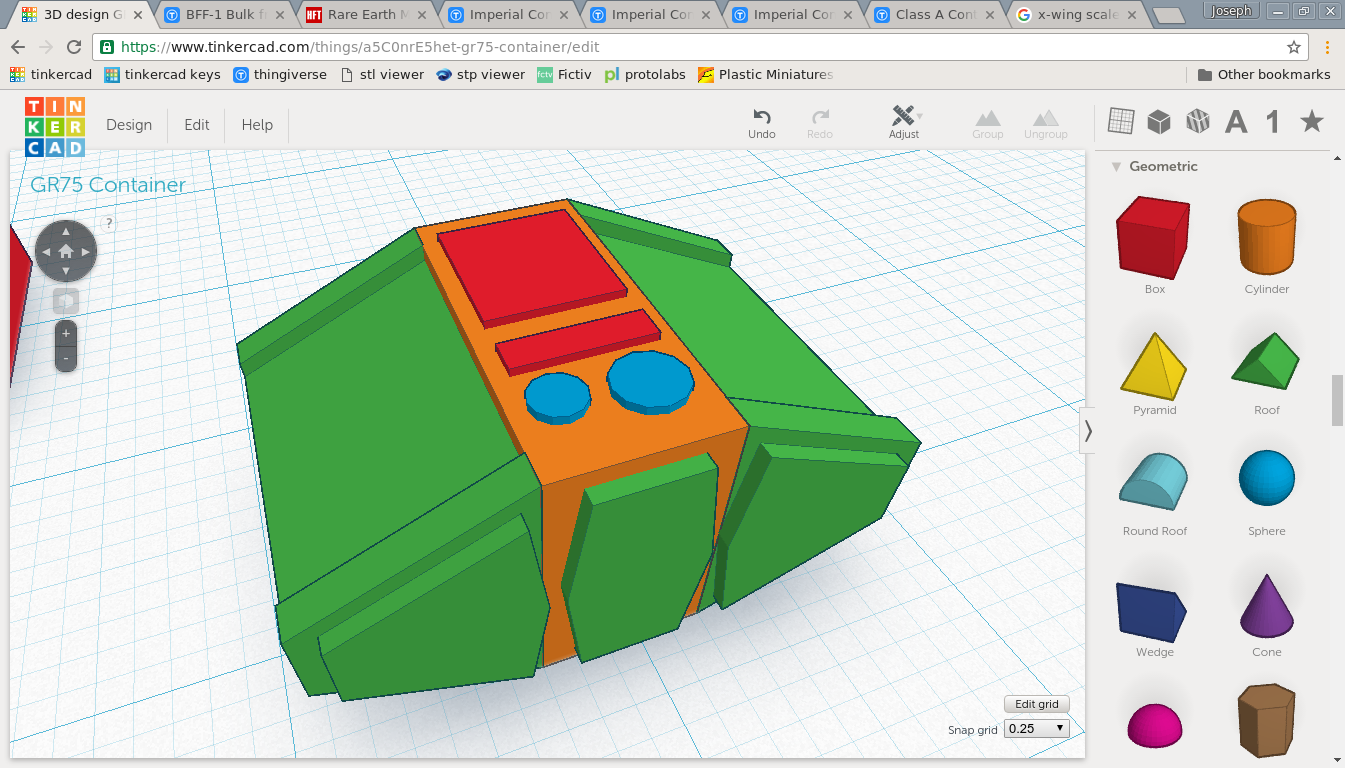
Next I added simple shapes above the top of the center box to give it texture, just like the FFG model. Another bit of minute detail is that the one circle appears slightly smaller relative to the other on the original model, and I kept that here. Like the pads, these details are again sized keeping in mind the capabilities of many home printers. Mine has a 0.5mm nozzle, which is fairly common. That means it more or less produces a 0.5mm wide path. It’ll try, but it can’t realistically and reliably print features below 1mm resolution, essentially a wall made by a path going out and back. So that’s my usual size threshold in making small details like this, the smallest circles and boxes are 1mm. That turns out to be fine though for throwing in vague details like these.
Once that was done I duplicated the front pads and full-size wing rib and shifted the copies to the rear. From there I grouped all the pieces of the wing, duplicated them, shifted them to the other side, and mirrored them.
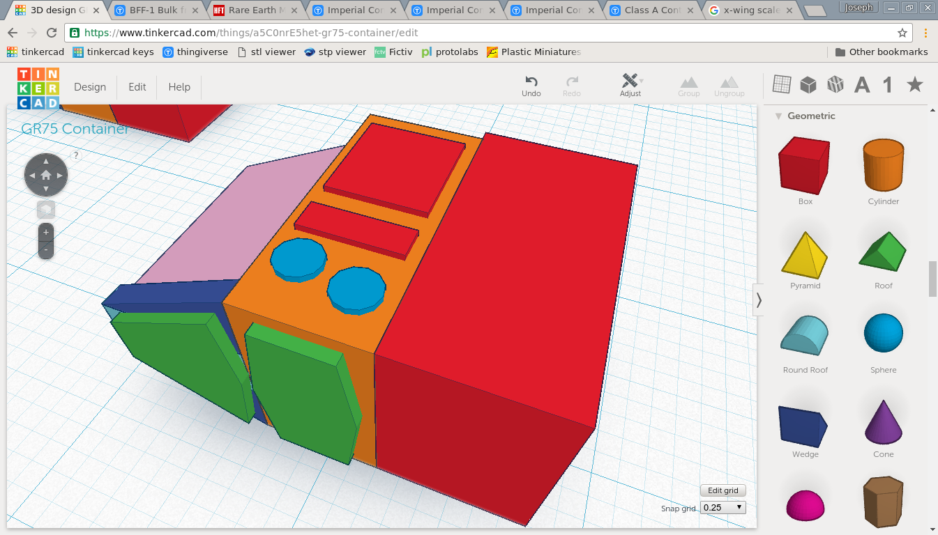
Adding bits on top for texture.
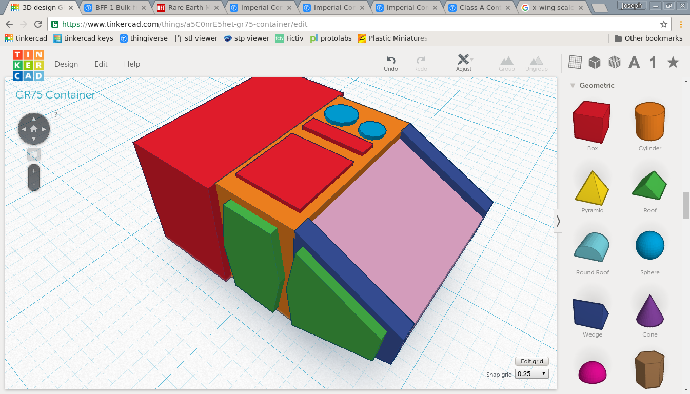
Copying the pads and full size wing rib from the front to the back.
Duplicating the wing to the other side.
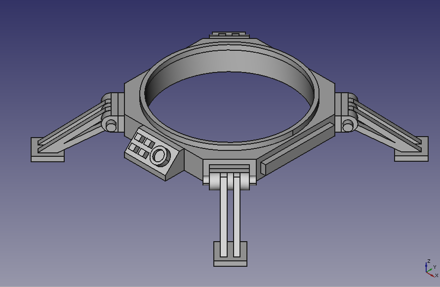
The modeling of the piece is now essentially done. All that remains is to create a hole on the bottom for a flight stand peg to hold the pod off the base, and group everything together to form a single solid.
The hole is simply a cylinder center aligned on the central box, switched to a hole, and grouped in. One small note here about TinkerCAD is that it doesn’t have many convenience functions. For example, there’s no functionality to choose a reference for an align action or to lock one piece down for aligning against (the button to lock pieces unfortunately—oddly—also prevents it from being used to align). So, if you select two displaced objects and center them, they’ll both move. Assuming the moving piece is smaller, the pattern is therefore to first align the piece that can be moved against the far extremity of the piece you don’t want to move, and then center them. Since the moving piece is now within the extent of the larger piece, the latter won’t move. In the next picture, this means aligning the cylinder against the right edge of the body, and then centering it. If the moving piece is larger then you need to position it manually or craft a more elaborate temporary construction.
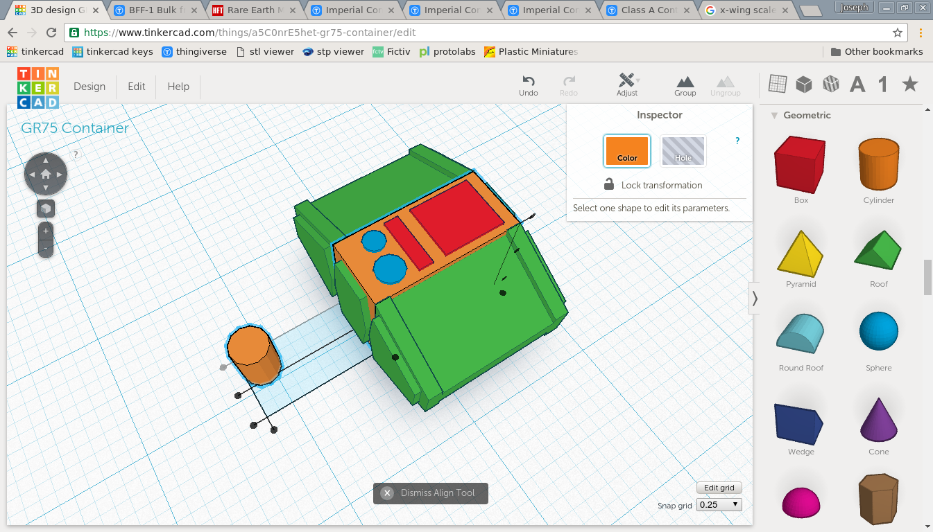
Centering a cylinder to become a hole for the stand peg.
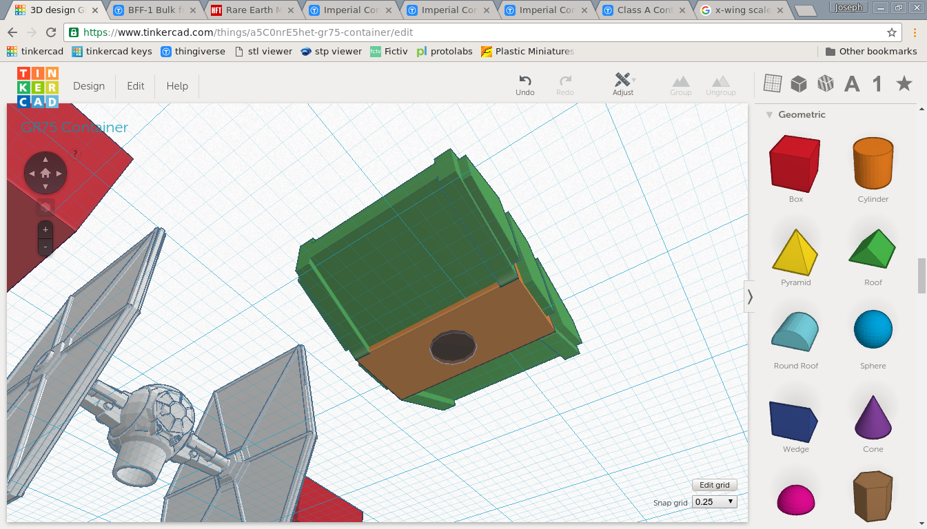
The hole grouped into the bottom of the center box.
That’s it! The cargo pod is now done.
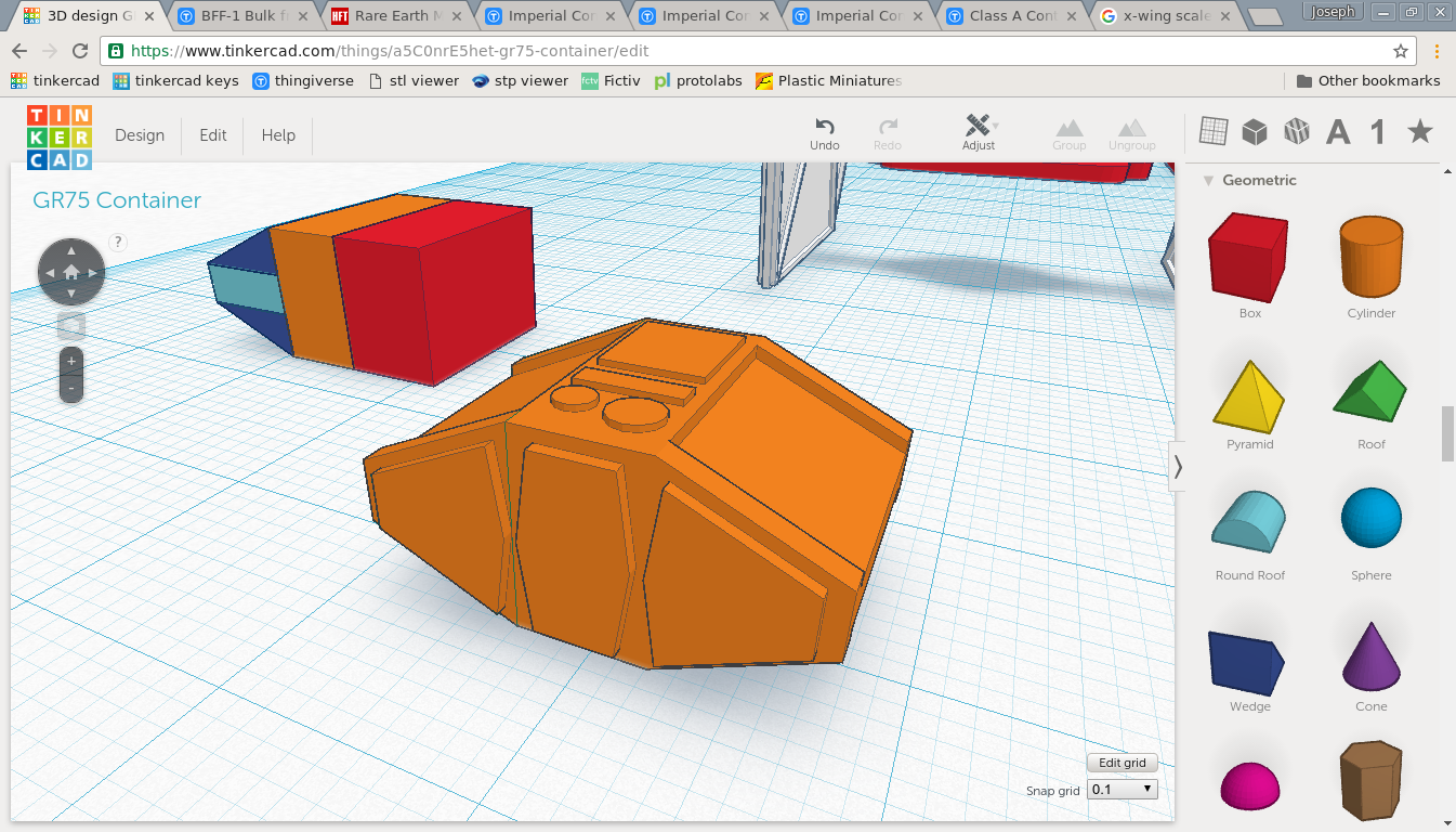
The completed GR-75 cargo pod.
Printing
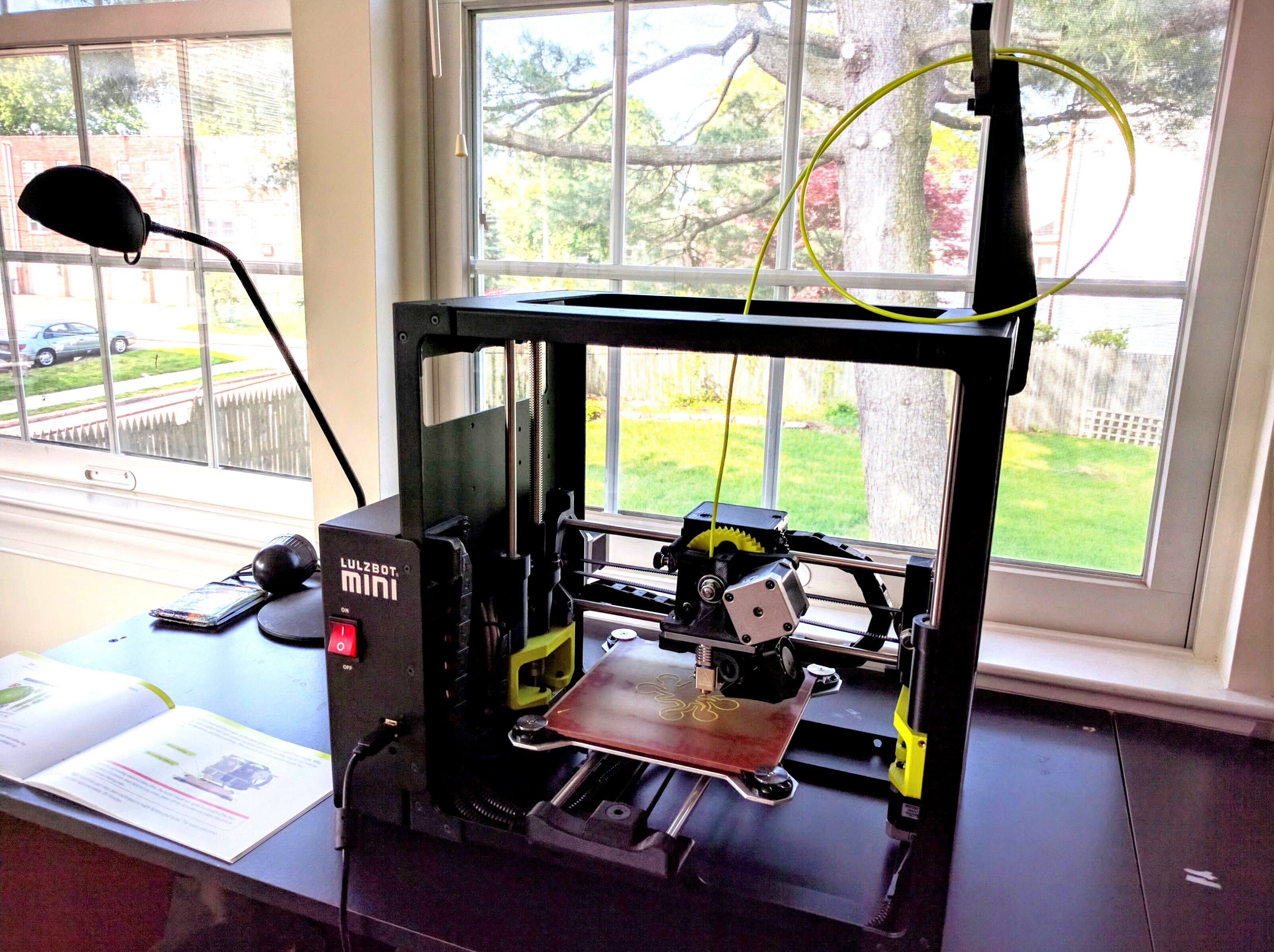
The next step is making a test print of the pod, base, and a simple flight stand peg. My printer is a Lulzbot Mini, which has been phenomenal to work with. Though I’m not an expert on current market offerings, it seems to strike a very good balance between cost, ease of use, reliability, print quality, print size, and time. An important observation is that it seems there are many printers now offering high enough resolution to print miniatures of acceptable quality. Some are even very low cost, down to ~$300. But it seems one of the biggest tradeoffs made in achieving that is that they print much more slowly. That’s probably fine to download and print parts, but in developing new parts from scratch could seriously slow down design iterations.
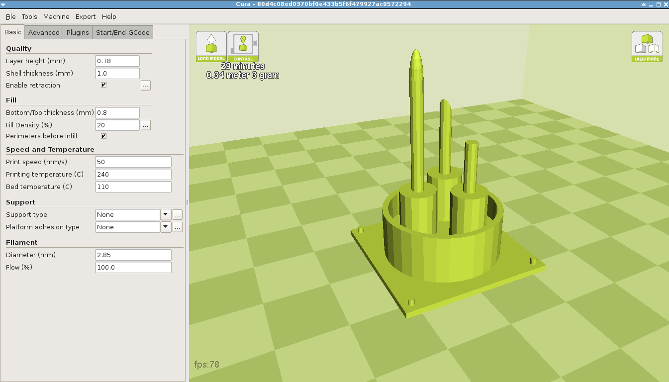
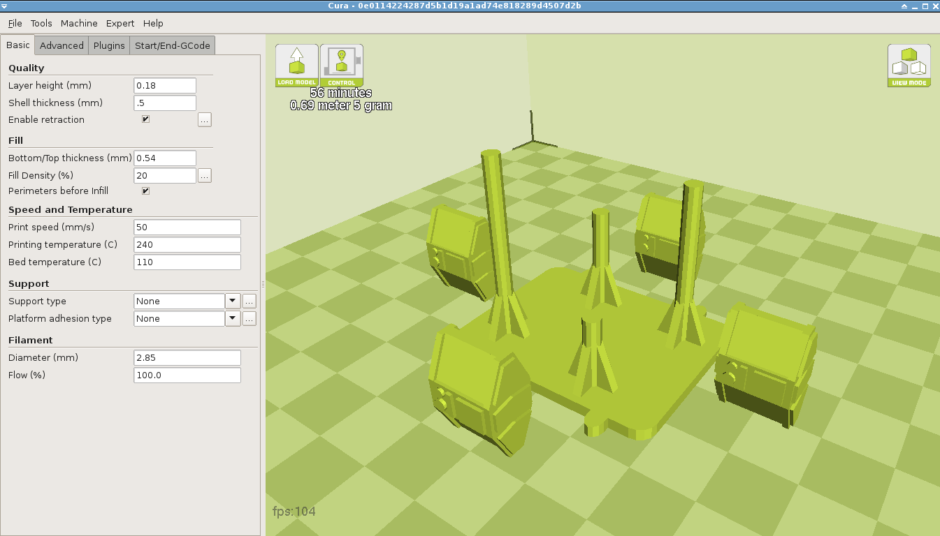
In any event, one of the cost tradeoffs made in the Mini is that it does not have an SD card reader and/or internal high level controller, it must have a computer connected to drive the print. So I use Lulzbot’s CURA distribution to slice objects into G-Code printer commands, and send that file to a Raspberry Pi running an Octoprint server which actually executes the job and can be monitored remotely.
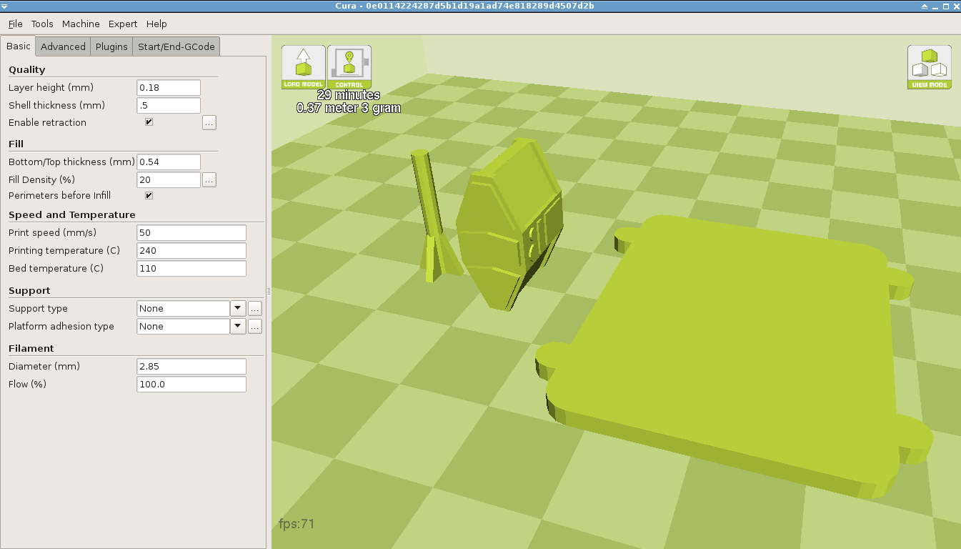
Slicing the test print.
Another logistical point is that I currently have my printer set up by a window, with fans to draw and push air out of the room and ventilate my workspace. Although there doesn’t seem to have been much study yet of health effects of 3D printers, ultimately fused deposition modeling is melting plastic to form a part. That typically creates toxic fumes, so I’ve been erring toward an abundance of caution as I use it heavily.
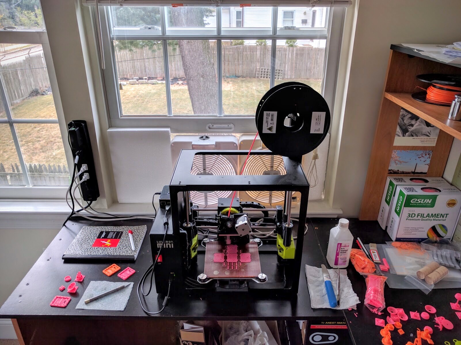
My current printer setup.
I’ve been exclusively using eSun HIPS filament for miniatures work, to great success. The resulting product has great resolution, is hard and strong, is easily cut and sanded, and takes paint great. A kilogram spool runs $24–40 on Amazon and can be shipped same day Prime. A part like the cargo pod and its base only uses literally a couple grams of material, so you can print an awful lot of miniatures bits per spool.
As referenced above, caveat upgrades, the Lulzbot Mini has a 0.5mm nozzle. After a fair bit of experimentation tuning settings for this kind of project, most of my prints are at 0.18mm layer height; 0.54mm bottom/top thickness; same initial layer thickness; 100% initial layer width; and 20% infill at 0.5mm shell or 10%, 15%, or 20% at 1mm shell. Those settings have struck a good balance between speed, quality, and strength, with very acceptable dimensional accuracy (mostly a challenge in the initial layers).
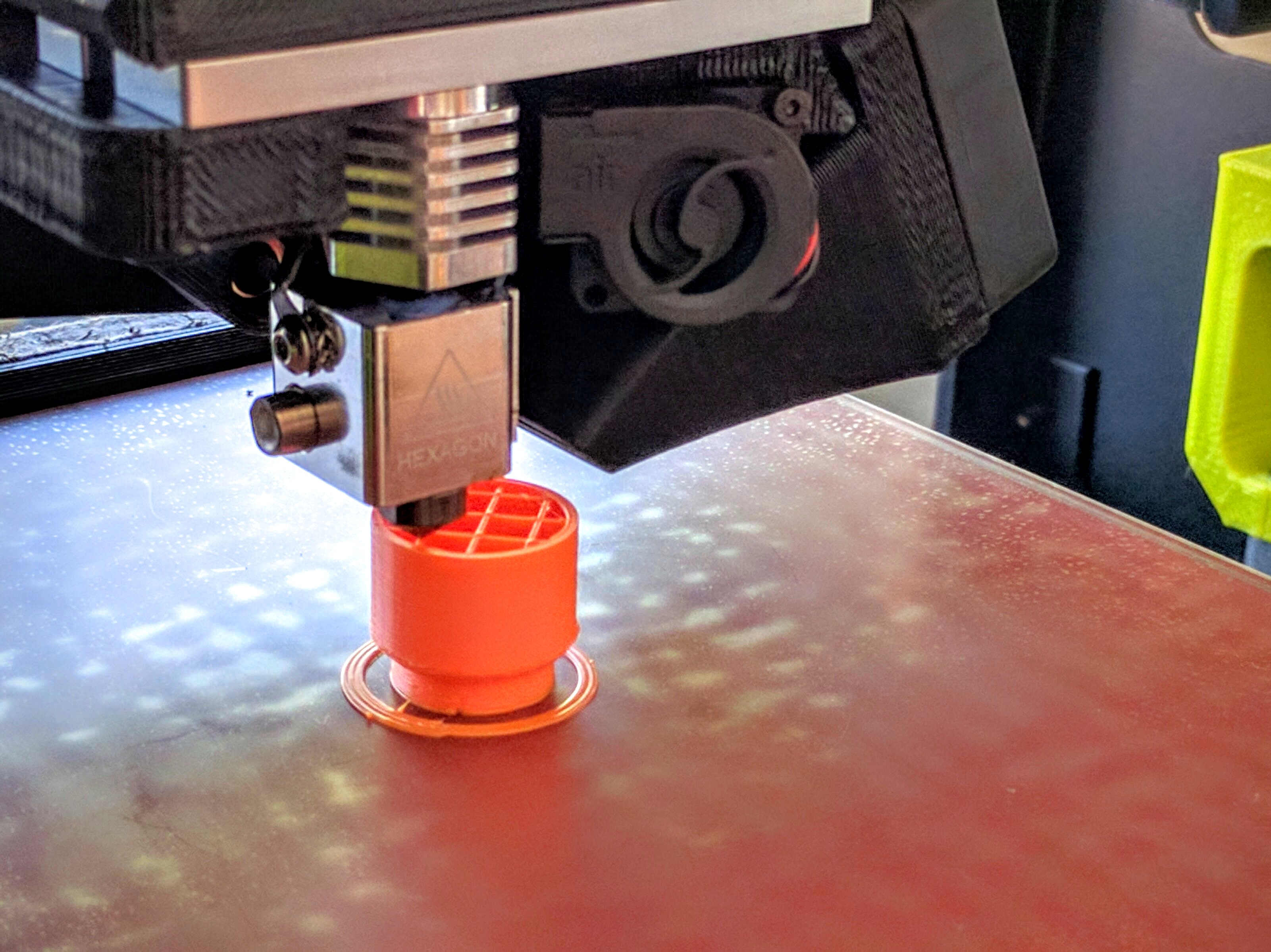
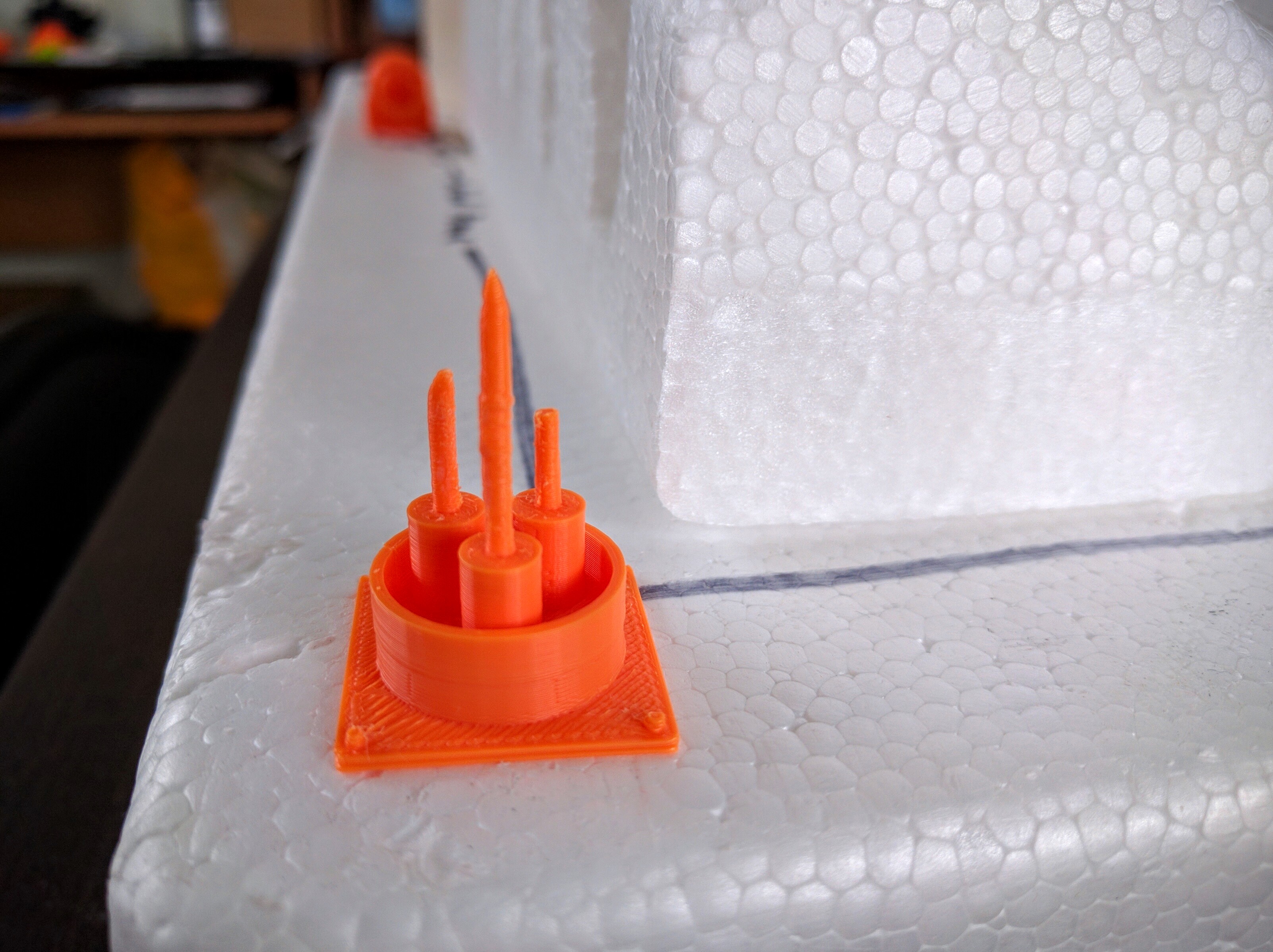
In the end, the first test print came out excellently! The part came out very cleanly and definitely looks like the cargo pods. The only changes made were to raise the top details from 0.25mm to 0.5mm tall so they’d not be lost in paint, and to increase the flight peg diameter to 3mm. I’d expected to have to do that, but was hoping in vain that the thinner 2mm would magically work. It looks good and would be perfectly fine for at-home play, but I need these pieces to work in a public event setting where they’re not being babied, so I had to accept the 2mm pole would be too easily snapped. I also ran the test with a separate flight stand peg so that in case it was useless, the base would still be useful somewhere. However, the final design integrates the peg and base to make a solid connection with no gluing required.
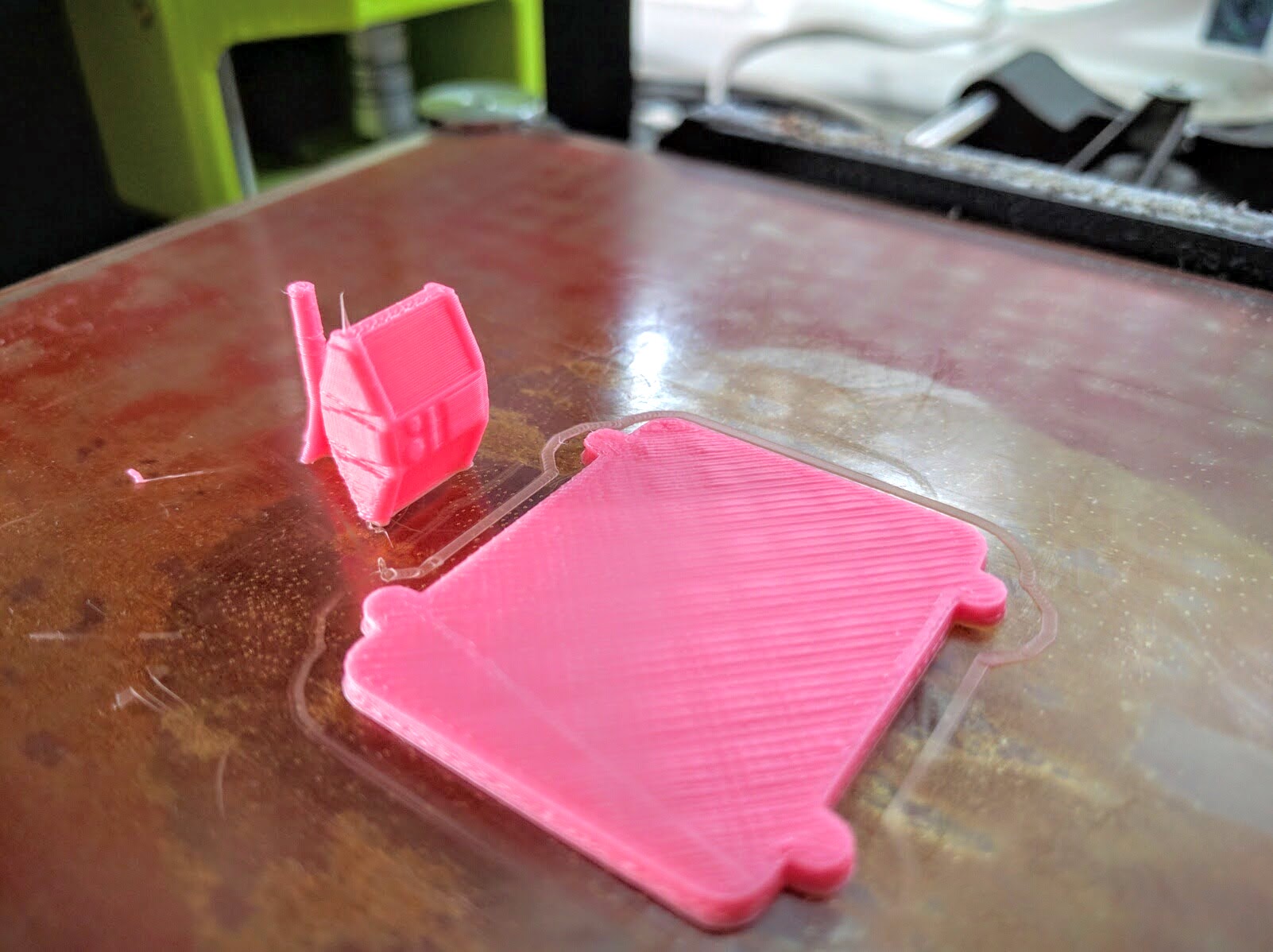
First print: Success!
Conclusion
After that was just making a few bases with different numbers of flight pegs, and the project was all wrapped up. I now have a sweet 3D cargo supply container token that matches my beloved GR-75 in 1/270 scale, and have started printing out piles of them.
Again, these designs have been uploaded to Thingiverse as a free download. Drop a line if you make use of them, or have any questions about this walkthrough!
Final design mockup of a cluster of cargo pods; prints are made as one base piece (red) and a bunch of pods (orange) that fit onto the pegs.
Print layout for a stand of 4.
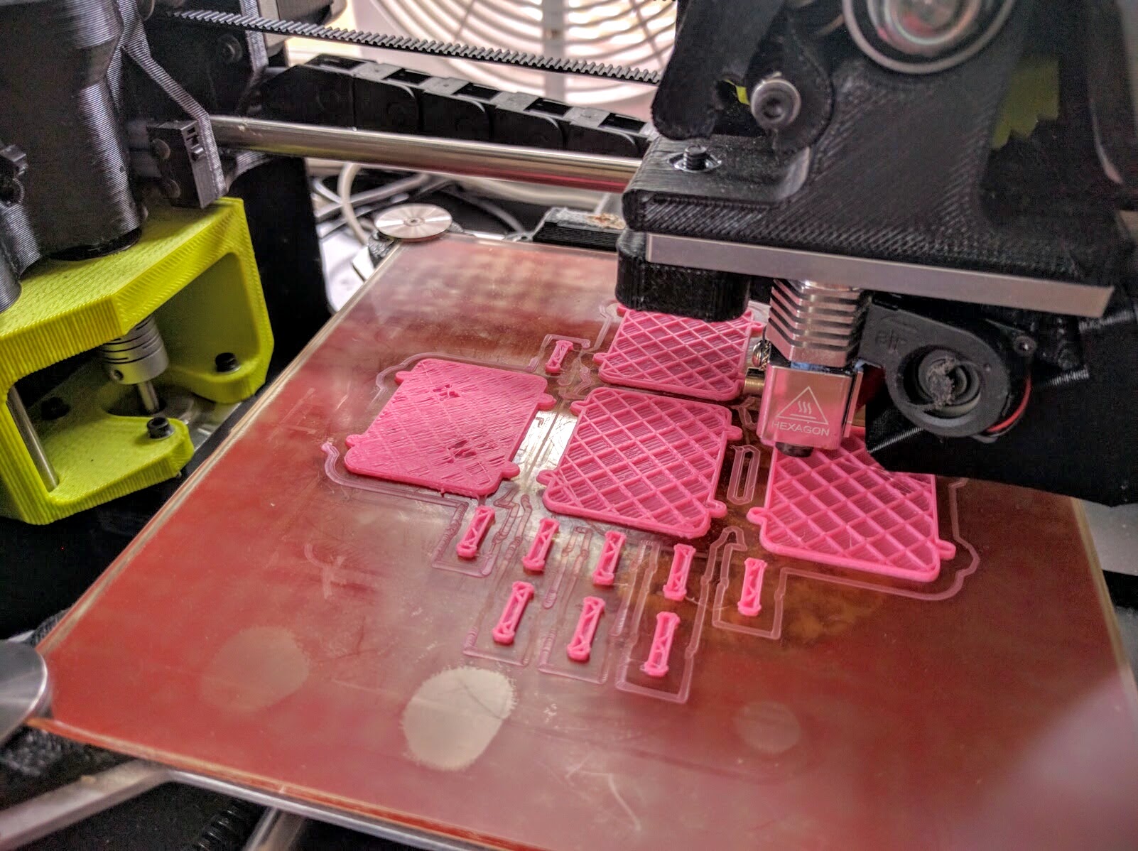
Printing an initial batch of tokens.
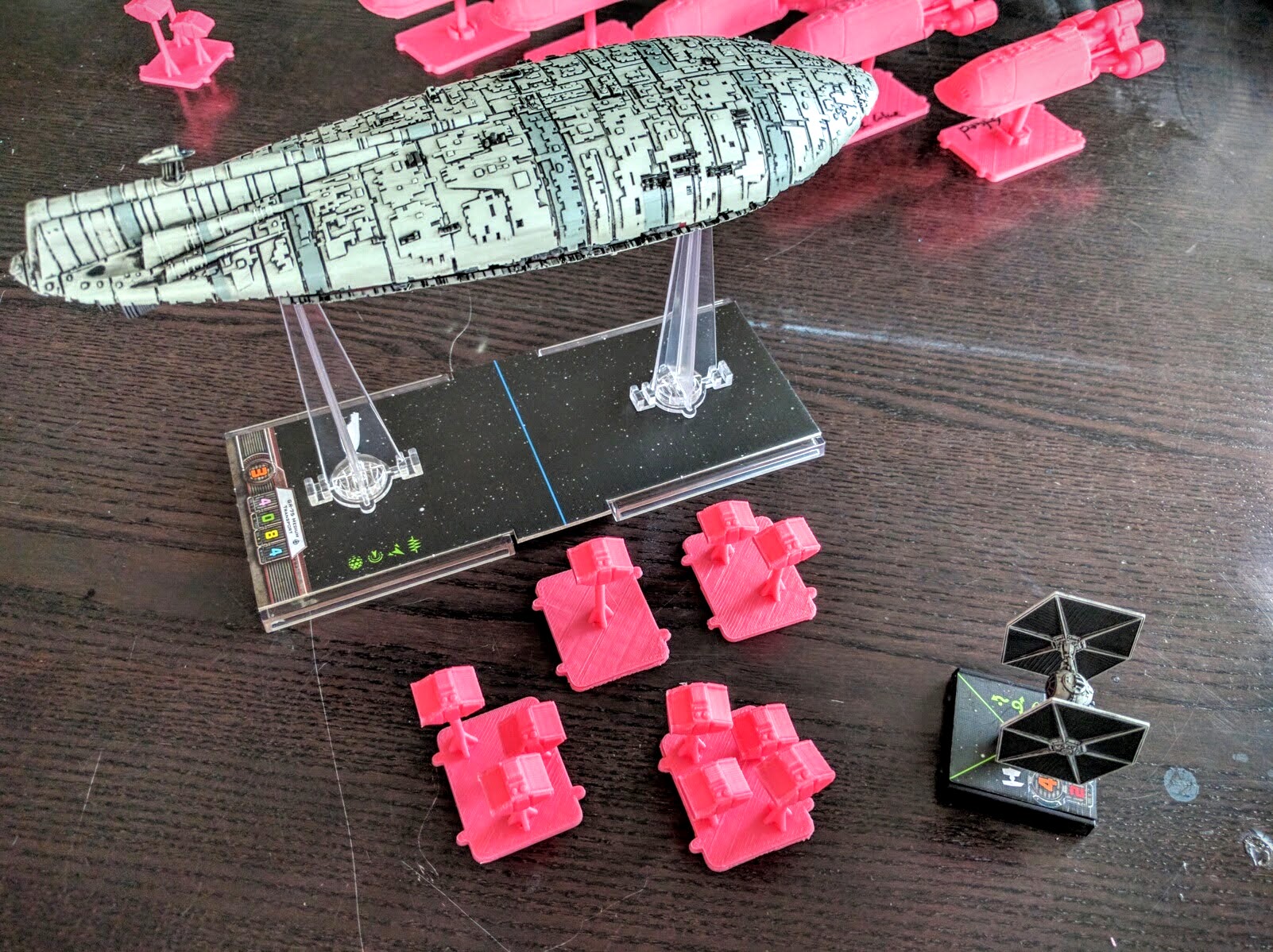
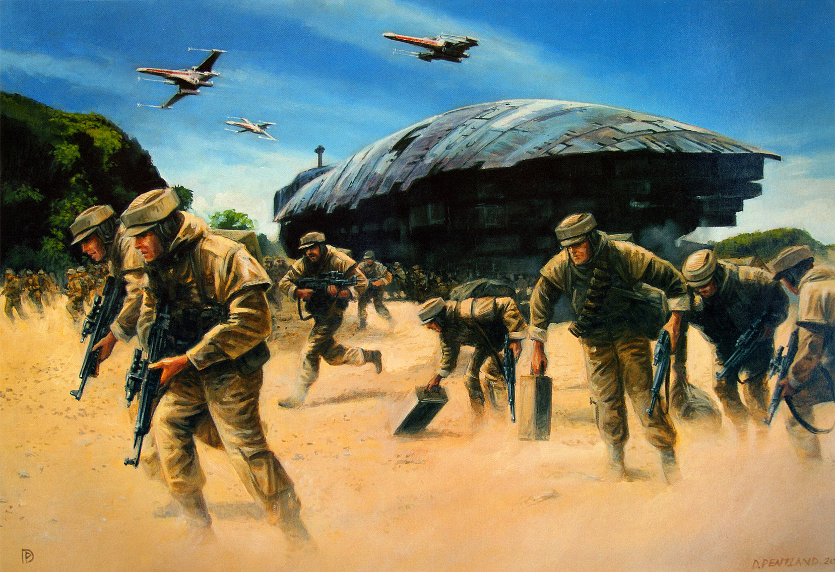
Cargo pods and their mothership under attack!
Supply depot.
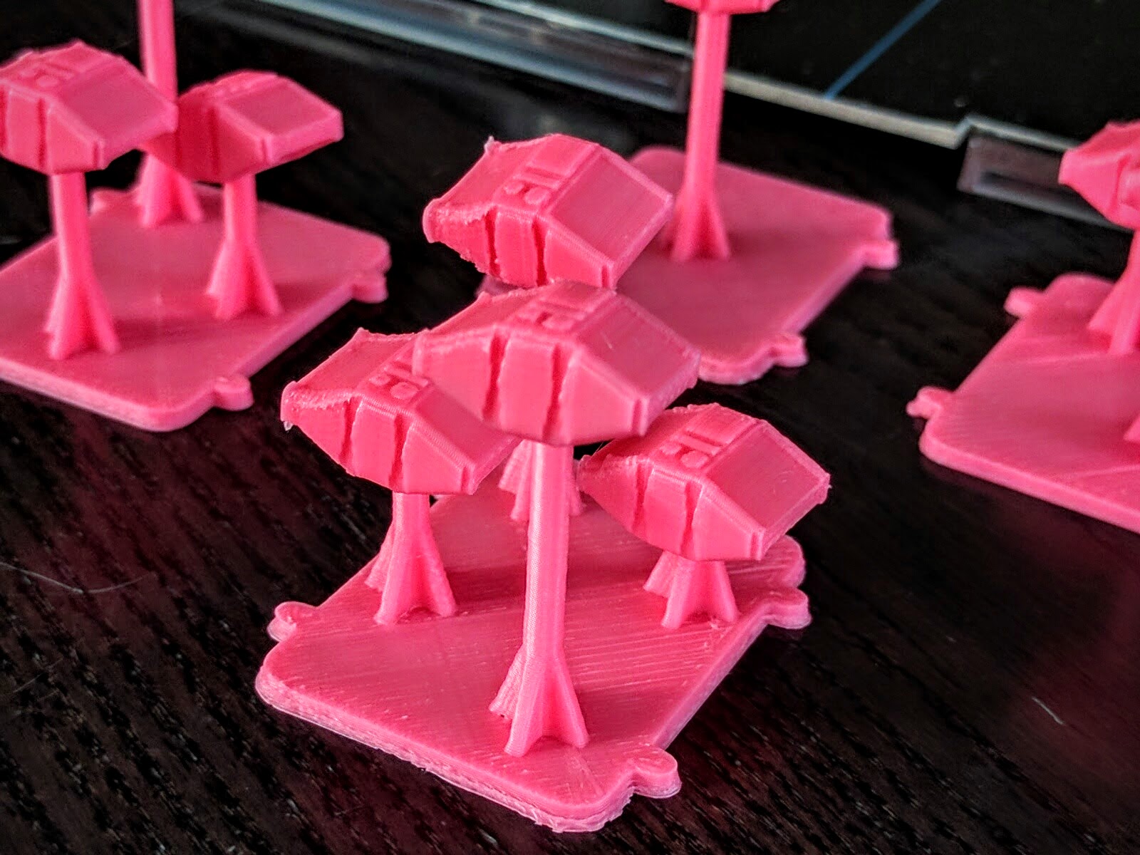
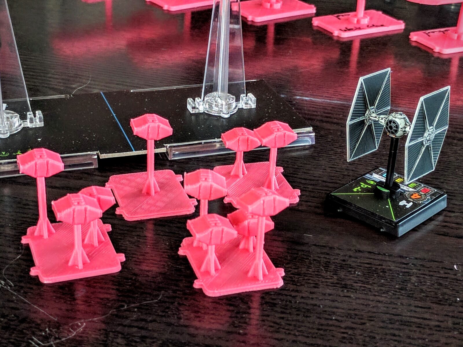
Extreme closeup. These parts have not been cut, trimmed, sanded, glued, or otherwise cleaned up in any way yet, this is straight off the printer just popping pods onto pegs.