I’ve got 4 square feet covered with this set now, so two more large pieces or three smaller ones should cover a standard 40k table very well.
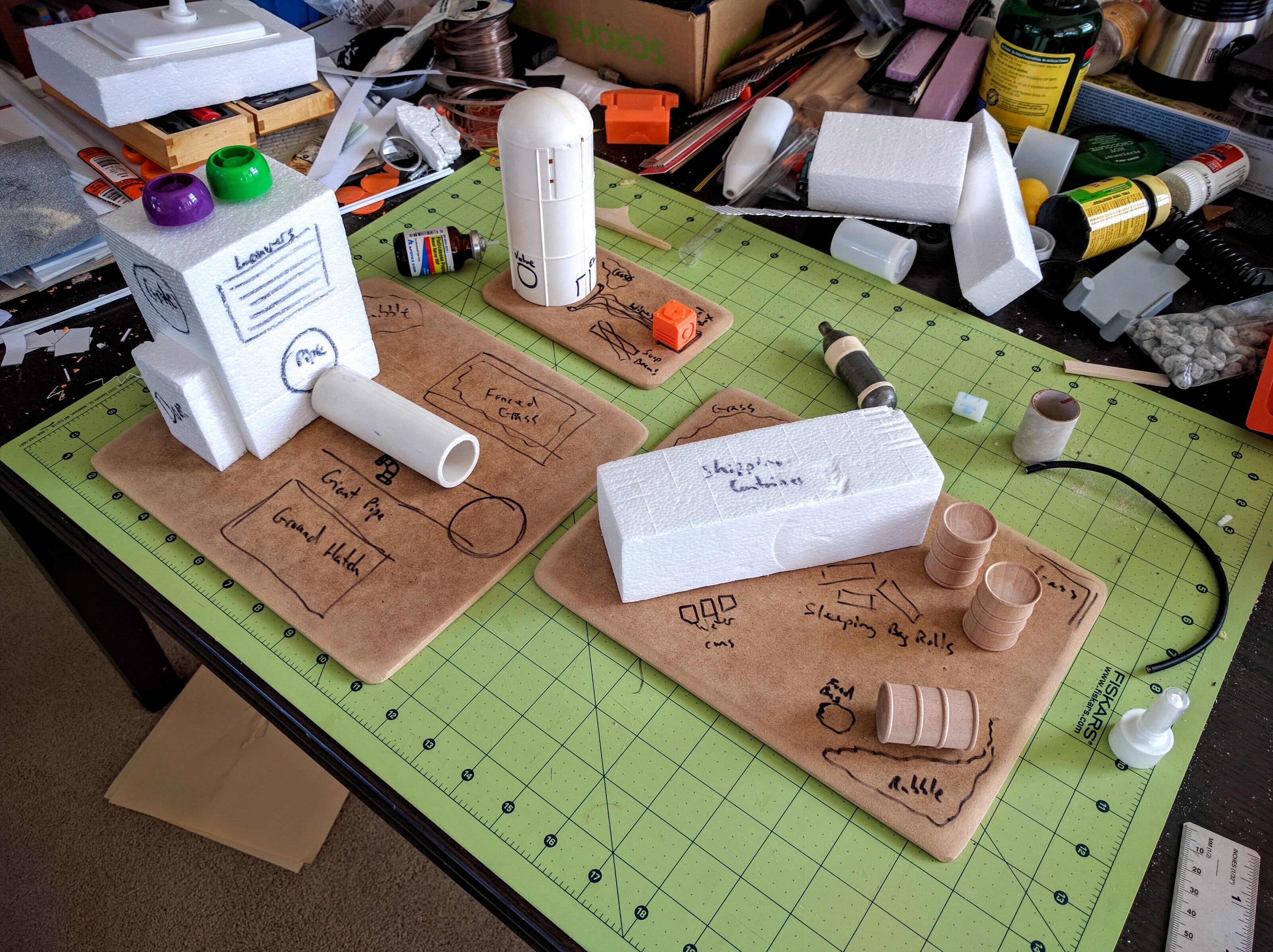
Initial layout sketching; the piece on the right has not gotten more attention yet.
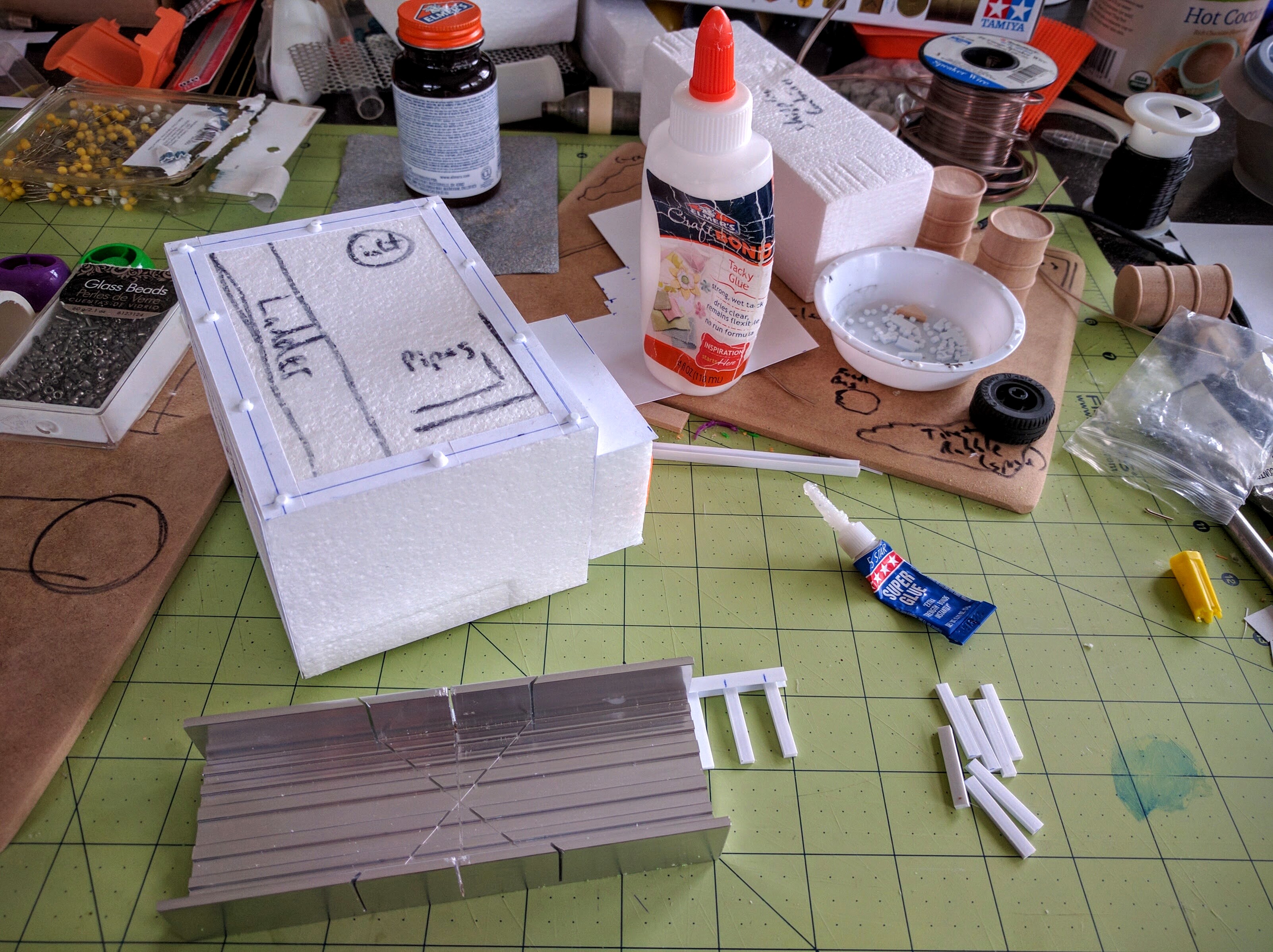
Building a ladder.
I have a tutorial here on how I’ve been constructing ladders for this set.
Printing some doors and other pieces (not all for these builds).
I designed the majority of the 3D printed pieces used here, half of them specifically for these buildings and the others as generic bits. The other three printed pieces I found on Thingiverse (the door hatch, ground hatch, and small circular hatch).
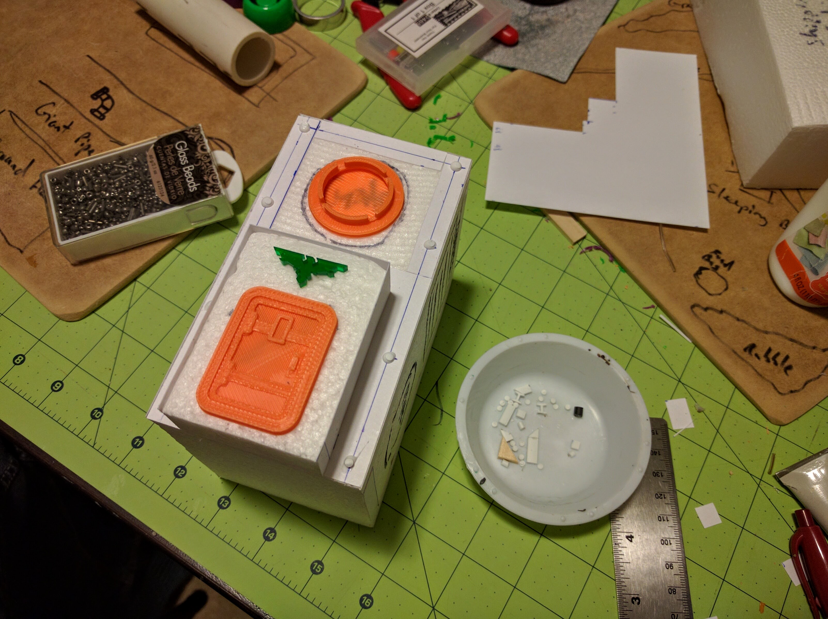
Gluing on rivets and widgets.
The green aquila is an acrylic cut from Greenman Designs. I picked up a bunch at NOVA a few years back specifically to use like this, as details above doors.
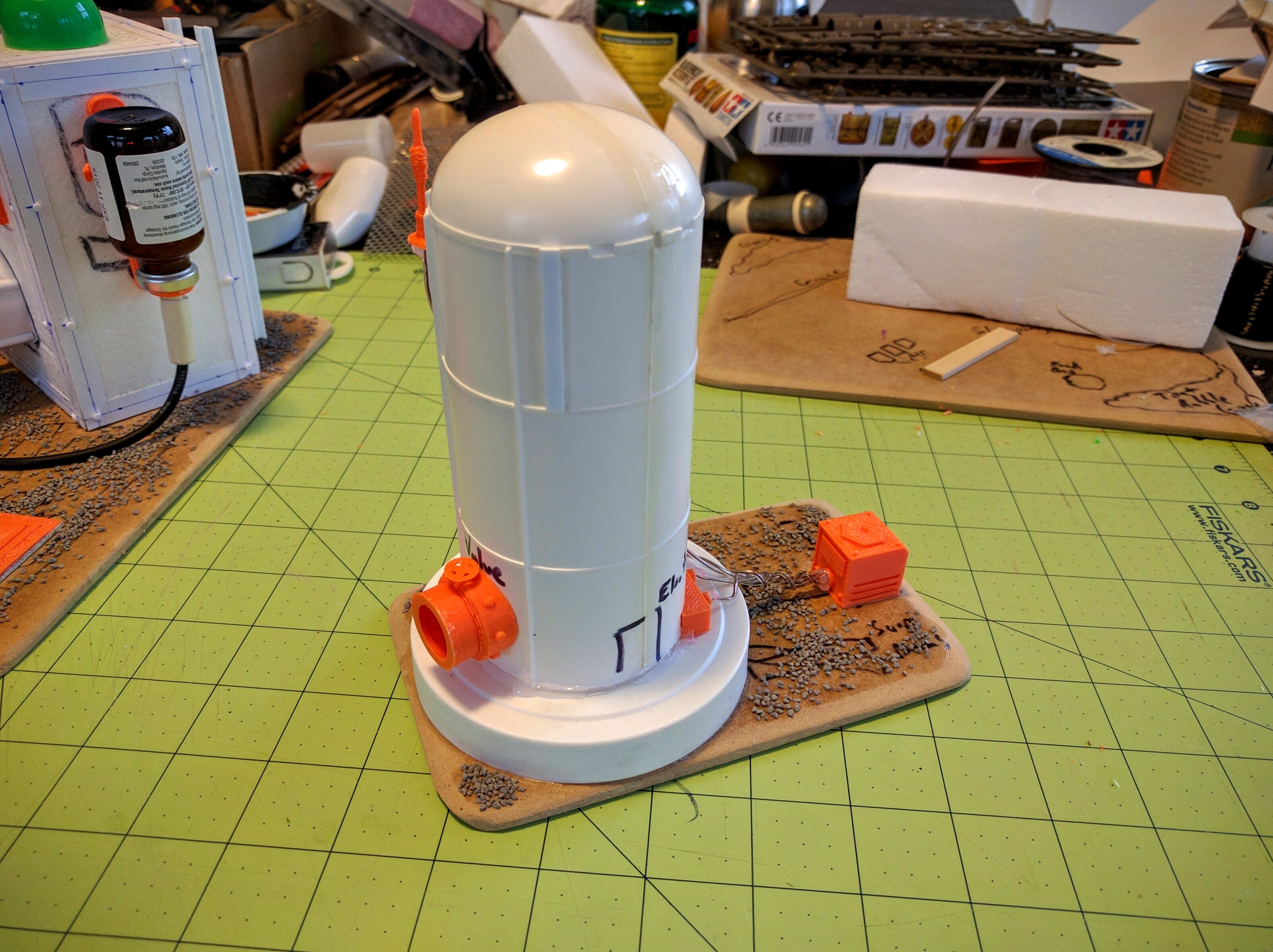
The silo (left).
The silo (right).
Outlet valve piece, shaped to fit the silo.
I designed each of the bright orange 3D printed bits on this silo. The mechanical box is a generic bit I’m using in a couple places. The other three were specifically designed for this piece, they’re shaped to fit the curve of the silo. I’m pretty happy with how the output pipe in particular came out, though I need to work on the valve handle. Fortunately it’s very identifiable as-is. The silo itself is half of the main booster fuel tank from a space shuttle model I’ve had kicking around forever, with the cap from a jar of Gatorade powder providing the pedestal base.
The pipeworks (front).
The pipeworks (back).
Details of the pipe and tank tubing.
The pipeworks building came out very well. I changed the composition at the last minute as this diagonal layout just looked more interesting. The change cost me the space for a little fenced-in mysterious patch of grass I was going to have, but was definitely worth it. The pipe itself is just PVC plumbing pieces, with some Plastruct bits glued on and tape wrapped around to add detail. The green barrel is from a Tamiya 1/35 Allied Vehicle Accessories kit. I was glad I had that on hand, as the wood barrels used on the other pieces are much larger and would distract from the building. I especially enjoyed designing a printed part to be a collar ring and arm holding the nasal spray bottle as some kind of tank hanging off the side.
Just a couple more pieces to make, and then a couple guys from the club are coming over this weekend to hopefully get it all painted!
Continuing on my Medea Refinery terrain build for our LibertyHammer event, I’ve finished up Smelt Furnace #17 to go along with Primary Pump Station A1. I’m pretty happy with it and think it will serve well as a big LOS blocker with a good amount of detail. Hopefully the remaining pieces for this terrain set come together much more quickly. They currently consist mostly of random interestingly shaped trash and won’t be as detailed.
Front side.
Back side.
The furnace was made by a combination of throwing rubbish together, traditional scratchbuilding, and 3D printing. The foundation and major heat sink are just trash packaging foam. The big smoke/heat column is plastic trash from a broken pool filter. I hope to make an insert for it with billowing smoke out of dyed cotton balls but have not started on that yet. The ladders were constructed as described in this tutorial. The small antenna cluster, tank stand, and rooftop mechanical box are 3D printed parts I designed, available as free downloads from those Thingiverse links. The other printed parts are downloads I found. A walkthrough of designing and printing 3D parts based on the antenna cluster is posted here.
Rooftop orbital antenna.
Rooftop local antenna cluster, not glued down yet here.
Side louvers, constructed the old fashioned way…
Side inlets/outlets and machinery access.
Product and supplies ports and some ribbing on the structure.
Some kind of doodad on the roof.
Getting into using 3D printed parts for this terrain was interesting, and somewhat bittersweet. Though not astounding, I think I have above average scratchbuilding skills when I set my mind to it. But I can easily see them atrophying a bit as I drift into making more and more elements on the printer. Still though, you do need good fundamentals to pull it all together, and especially to make big pieces. And certainly there are a lot of things I can model and print much faster and better than I can construct by hand, let alone downloaded pieces.
More to come as I wrap up this set over the next week for a club terrain build/paint workday over Memorial Day weekend!
Recently I got a 3D printer and have been having a great time with it. My more general thoughts about the technology I’ve already posted. Here I present a quick walkthrough of one of my immediate, highly critical and urgent, applications for the tool: Making detailed parts for miniatures wargaming terrain.
Design
Recently I scratchbuilt a small facility for a new set of terrain I’m working on for my club’s upcoming LibertyHammer event. One of the little bits built to provide some detail and texture to the model’s overall look is a simple antenna cluster.
Scratchbuilt antenna array.
That prototype turned out pretty well, so now I’d like to have a bunch of them to stick on various buildings in the set. They’re not hard to make so they’re not worth the hassle, cost, or time to resin cast (though it would be straightforward to do so because of the verticality and flat bottom plane of the shape). With the 3D printer though I can make a tradeoff: It’ll actually take longer to produce, almost 30 minutes on my printer at high detail versus maybe 10 minutes for me to make by hand. But I can do other things in that time, and they’ll be more consistent, more detailed, and I don’t have to scrounge around for supplies and components.
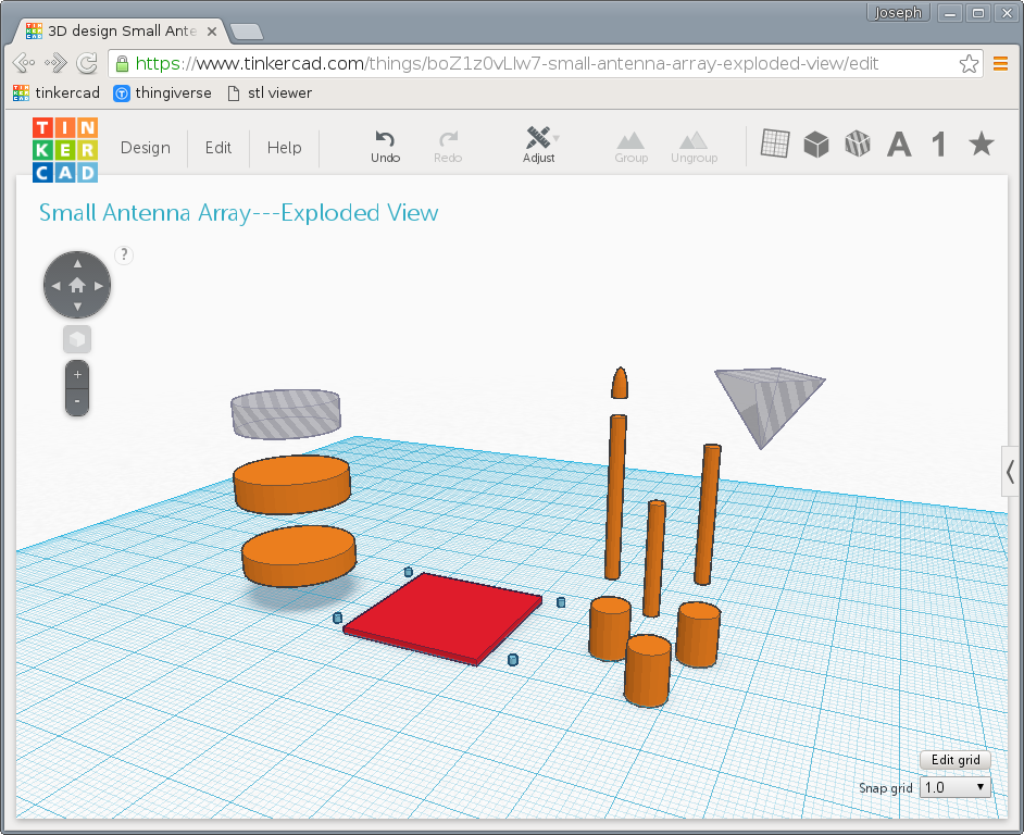
To do so of course I have to create a 3D model. For this project I used TinkerCAD, a simple browser-based 3D computer aided design (CAD) program from Autodesk. The end result is faithful to the scratchbuild, with just a few more details.
The finished antenna array in TinkerCAD.
TinkerCAD is essentially a constructive solid geometry modeler. Its core operation is constructing complex shapes by adding and subtracting simpler shapes to and from each other (unfortunately it does not seem to support the third constructive geometry primitive operation, intersection). For example, to put a hole through a cube you take a cube and a cylinder and subtract the latter. To make a farm silo you would take a cylinder and add a sphere sunk halfway into the top.
One advantage of this paradigm is that the final product is guaranteed to be solid. In mathematical terms, every point in space is completely determined to be inside, outside, or on the surface of the shape. Intuitively, the 3D shape is watertight, there is no way to pass between the common sense exterior and interior. This property is critical because it’s essentially required in order to print a model. Although there are other approaches to working with solids besides constructive geometry, not all 3D modeling approaches are based on solid forms and may not guarantee that property and be as directly applicable to representing physical artifacts. For example, many tools oriented toward video game and animation modeling are based around manipulating arbitrary 3-dimensional meshes of polygons, which aren’t necessarily solid and may not be printable because no algorithm can determine what is inside and what is outside the piece.
Another feature of constructive solid geometry is that it’s comparatively easy to make many kinds of modifications to the part later on, because the sequence of steps and feature composition of the part is naturally retained in its model.
A downside of constructive geometry though is that it can be difficult or actually formally impossible to create some complex shapes. Fortunately though, the style is well suited to making many types of mechanical parts, as well as many kinds of wargaming models, especially mechanical or industrial terrain. The antenna cluster for example is mostly just a few cylinders of varying sizes, a base plate, a negative cylinder to create a pocket forming a partial wall around the antennas, and another pyramidal hole slicing an angle off the top of one antenna.
Constituent parts of the antenna array model. The gray semi-transparent parts are holes, negative shapes. The other colors have no meaning.
Printing
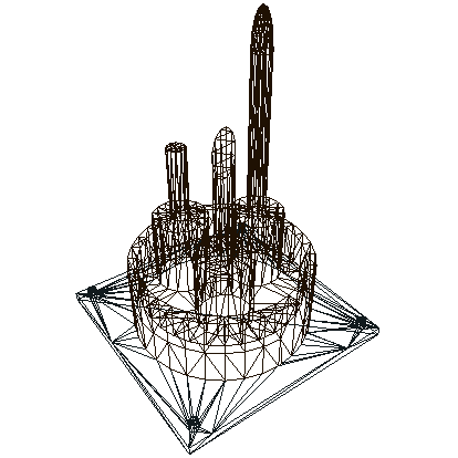
The part is then exported to STL, a STereoLithography file. This is one of the primary file formats common across CAD software and is ubiquitous in 3D printing. Stereolithography is actually one of the earliest forms of 3D printing, and the basic principles are still widely used, particularly for very high resolution printers. One of the reasons for the STL format’s enduring popularity beyond those early tools though is its simplicity: The entire model is represented as a collection of triangles making up a polygonal mesh. That’s essentially a lowest common denominator for working in 3D, so it’s easy for software developers to import and export.
View of the STL triangular mesh, from viewstl.com.
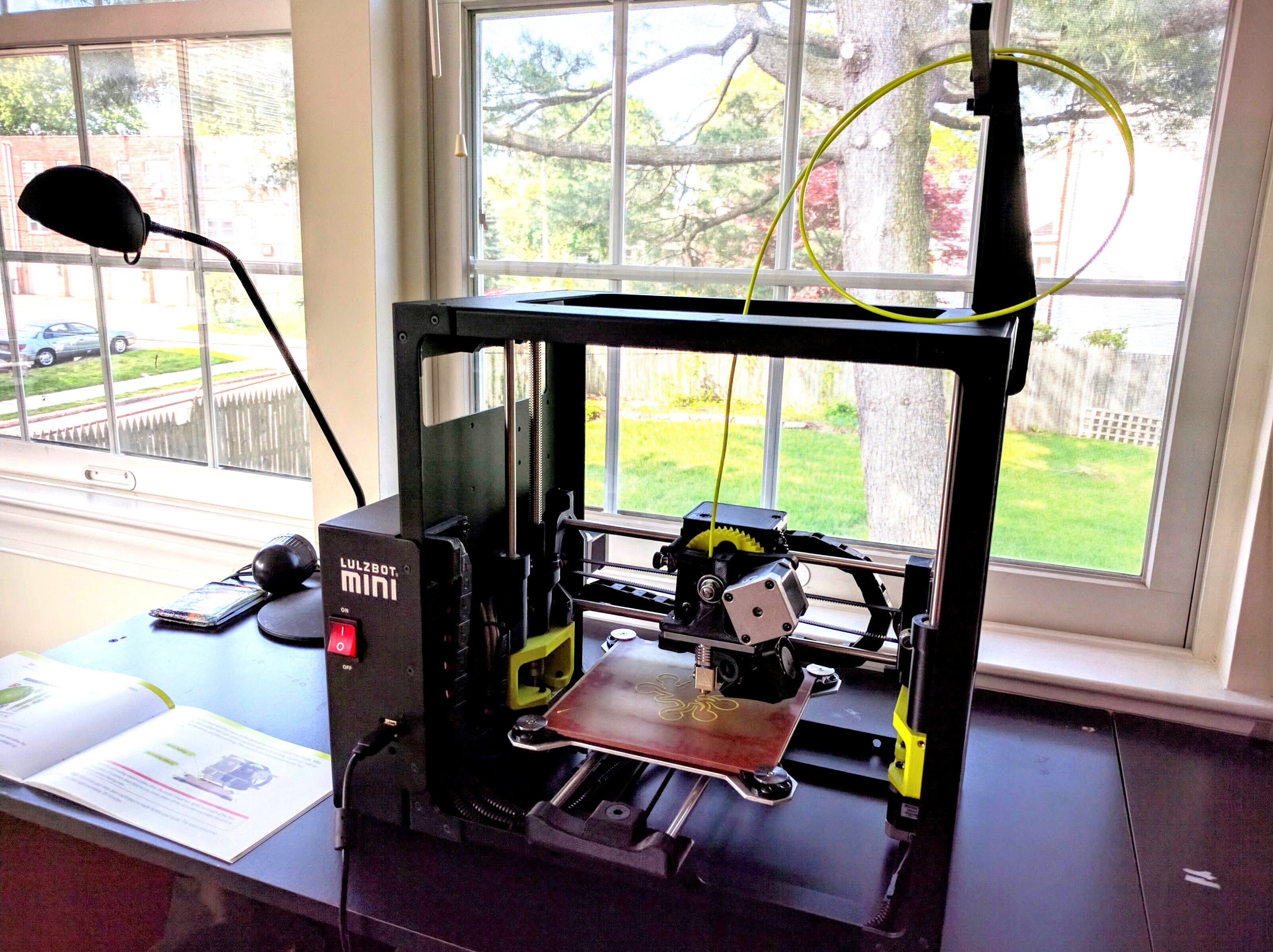
Like most home 3D printers, mine is a fused deposition modeler. A strand of material, usually some type of plastic filament but not always, is heated and extruded through the printer head. Servos move that printer head or part workbed around to outline and fill a single horizontal 2D slice of the part. The head is then moved up relative to the workbed to deposit another slice on top of that. Working from bottom to top, eventually a 3D part is constructed. Slicer software is responsible for taking the STL file and cutting the shape up into thousands of layers, then generating the movement commands to drive the print head.
My Lulzbot Mini.
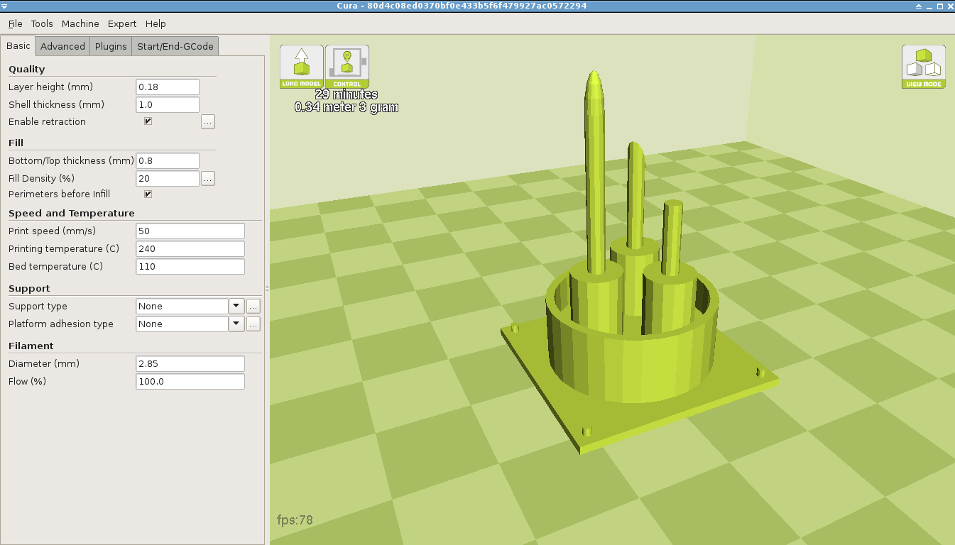
The antenna ready to print in Cura, a popular slicing and control package.
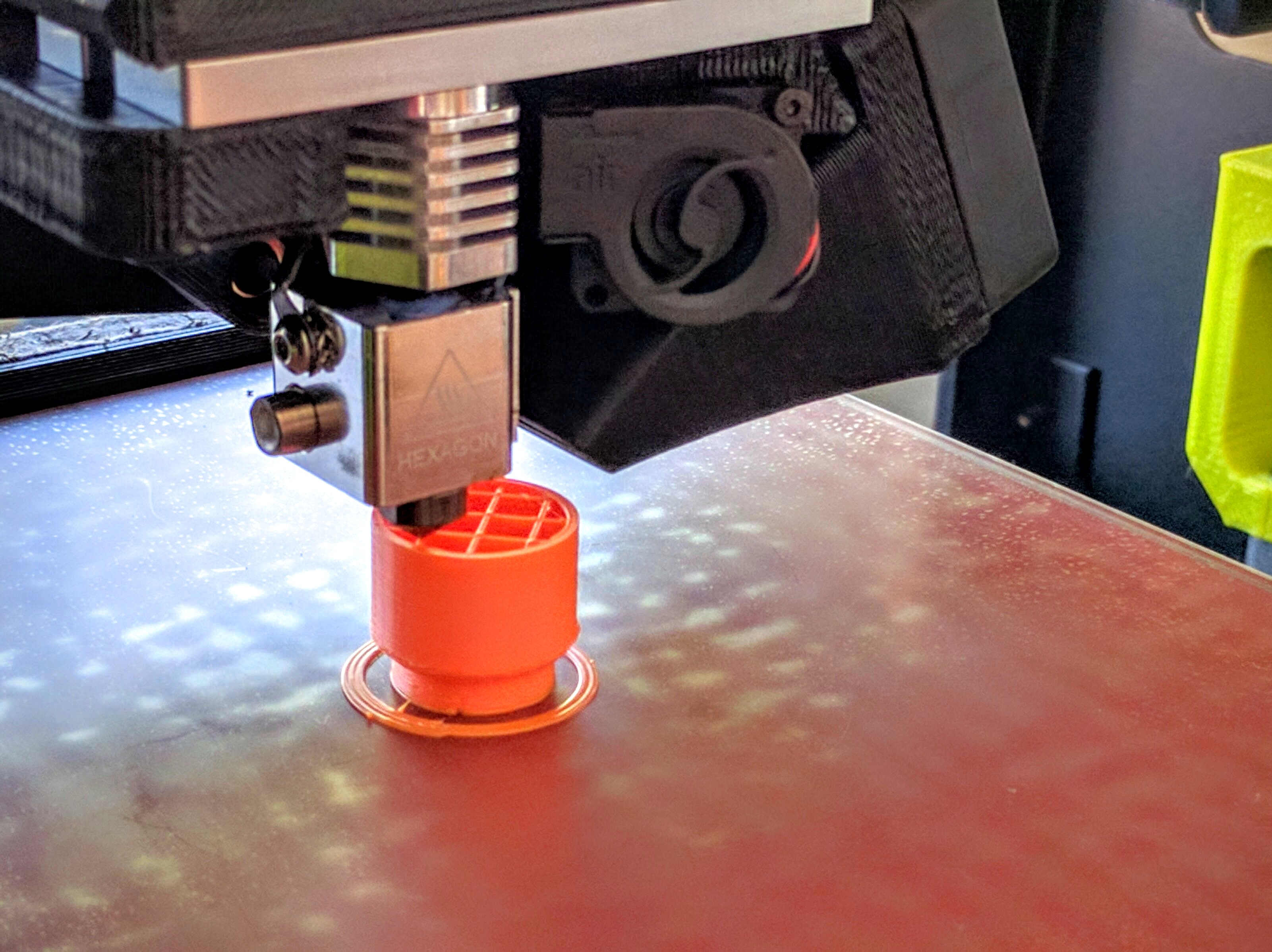
Printing a (different) part. Solid shapes are generally filled with an infill pattern, here the visible cross-grid, to maintain strength and form while dramatically reducing material and print time.
Of course there are numerous details beyond that quick summary: Material; layer height; printer speed; supports, rafts, and brims for enabling more complex shapes; and so on. But with some printers and software these days, and with appropriate models, it really can be basically as simple as just loading up the model and clicking “Print.” With my printer and settings this small antenna array takes about 30 minutes to print, and afterward I’ve got a sweet little terrain bit.
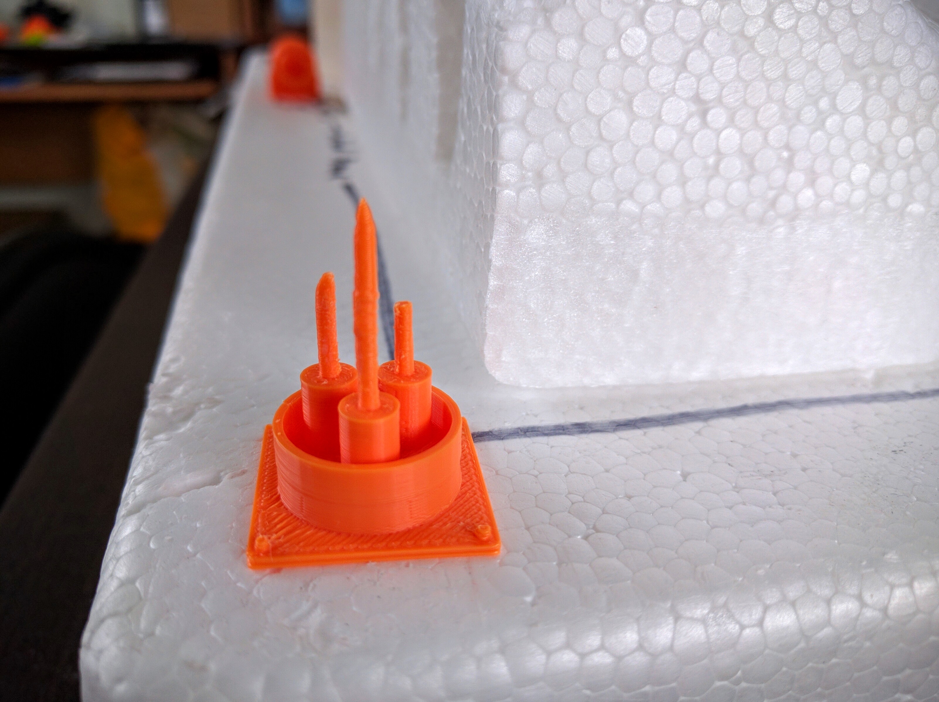
The printed antenna array.
How workable printed parts are depends a lot on material. I’ve been using high impact polystyrene (HIPS), which is frequently used in toys. It’s very hard, not rubbery or fragile at all, but carves nicely with a hobby knife. CA (superglue) and PVA (white glue) both seem to adhere well to it. I believe ABS, a more commonly used material, would be slightly harder to cut but otherwise have similar properties.
Of course, one of the beauties of this is I can copy & paste the design a bunch of times, hit “Print,” go do something else, and a while later I’ll have a bunch more…
Clones!
Conclusion
A few quick details to close out this walkthrough. My printer is a Lulzbot Mini, which I got because it met the right combination of price, resolution, and ease of use. In particular, it self-calibrates the dimensions of the workbed and cleans the print head before each run. Lulzbot maintains a version of Cura, one of the more popular open source slicing and control packages, patched with preloaded settings for their printers. Cura supports Linux and I was able to get it working under Arch Linux (not one of the directly supported distributions) with only a little fussing. The pieces shown here were printed using Lulzbot’s default “High” resolution printing, which amounts to a layer resolution of 0.18mm. Lulzbot claims the Mini can go down to .05mm resolution, but I have not played with that. I’ve been using HIPS filament, which I think is recommended for the Mini and toys & games.
The model for this antenna array is now freely available on Thingiverse. If you use it I’d love to see pictures, and I’d be happy to answer questions!
Update
A friend of mine is a professional model maker and caster, and we’ve been having a discussion about this article that may interest people. In a comment here I show more examples of printed parts and talk about costs and other tradeoffs in 3D printing for miniatures.